- A
i _
7_
B
L
-----_ 3" _,_--------- E --------------_
fi!i!i!b
19.(%
IIII
r
i
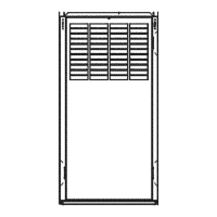
'-- TOP KNOCK-OUT
I __ FOR J DIAM VENT
20"
--G-q
KNOCK-OUT BOTH SIDES- 7
FOR J DIAM VENT/
J _ii .............................../
_ y II
',)) _ OIL INLET
_JA_'._" (BOTH SIDES)
i , , EgE% O'Ays
_- ..... \ / i II (BOTH SIDES)
] ""---_L -- rq_ _ .88 DIAM TYP
K
UNIT SIZE
105o12
t20-20
A
35
39-1/2
B
48-3/4
53
Dimensions (IN.)
C D E F G
30-1/4 16-5/8 20 22 12
32-1/4 18-3/4 24 28 12-9/32
Fig. 2--DimensionN Drawing
H
14
16
J
5
6
A98037
K L
1-1/2 1-3/4
1-5/8 1-1/2
INSTALLATION OF OIL
ANSI/NFPA 81:
BURNING EQUIPMENT
ANSlINFPA 211: CHIMNEYS, FIREPLACES, VENTS,
AND SOLID FUEL BURNING APPLIANCES
WARM AIR HEATING AND AIR
ANSlINFPA 90B:
CONDITIONING SYSTEMS
ANSl/NFPA 70: NATIONAL ELECTRICAL CODE
CSA B139:
INSTALLATION CODE FOR
OIL BURNING EQUIPMENT
CA8 C22.1: CANADIAN ELECTRICAL CODE
Only d-ie latest issues of these codes should be use& and are
available l_'om either _he National Fire Protection Agency, Bat=
teryrnarch Park, Quincy, MA 02269 or The (anadian Standards
Association, 178 Rexdale Bird, Rexdale, Ontario M9W 1R3
Recognize safety irRormation. This is the safety°alert symbol z_
When you see this symbol on the furnace and in instructions or
manuals, be alert to the potential for personal injury.
-->
Understand the signal words DANGER, WARNING, CAUTION
and NOTE. These words are used with the safety-alert symbol.
DANGER identifies the most serious hazards which will result in
severe personal injury or death. WARNING signifies a hazard
which could result in personal injury or death CAUTION is used
to identify unsafB practices which would result in minor personal
inju_ or product and property damage NOTE is used to highlight
suggestions which will result in enhanced installation, reliability,
or operation.
INTRODUCTION
)'he model 58CMA Furnaces are available in 2 sizes. Each size
unit is capable of 3 heat/airflow combinations by a simple nozzle
change. Unit 105=12 covers inputs of 70,000, 91,000, arid 105,000
Bmh, and unit 120o20 covers inputs of 119,000, 140,000 arid
154,000 Btuh This eliminates the need to stock 6 separate units
This furnace is a multipoise unit. It may be installed in the upflow,
downflow or horizontal configuration.
The [_l_rnace is shipped as a packaged unit, complete with burner
and controls. It requires a line voltage (115 vac) connection to
control box, a thermostat hook-up as shown on wiring diagram, oil
line connection(s), adequate duct work_ and connection to a
properly sized vent.
 Loading...