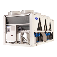
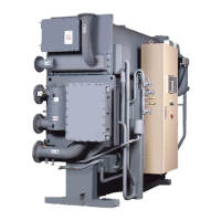
ONE-PIECE UNIT
OVERALL DIMENSIONS (ft-in.)
16JB 010,012,014 018,021 024,028 032,036 041,047
A 168-10
7
⁄
8
9 168-11
3
⁄
4
9 178-0
1
⁄
8
9 168-11
7
⁄
8
9 178-2
1
⁄
4
9
B 38-8
5
⁄
8
9 48-5
1
⁄
8
9 58-1
1
⁄
8
9 68-3
1
⁄
4
9 78-59
C 78-3
1
⁄
2
9 78-9
7
⁄
8
9 88-9
1
⁄
2
9 108-1
1
⁄
4
9 118 -6
1
⁄
8
9
OVERALL DIMENSIONS (mm)
A 5153 5175.2 5184.8 5178.4 5238.7
B 1133.5 1349.4 1558.9 1911.4 2260.6
C 2222.5 2384.4 2679.7 3092.4 3381.4
NOTE: Allow 148-49 (4368.8 mm) for tube removal when locating machine
(either end).
TWO-PIECE UNIT
OVERALL DIMENSIONS (ft-in.)
16JB 054,057 061,068
A 218-11
1
⁄
4
9 218-8
1
⁄
8
9
B 68-4
3
⁄
4
9 78-4
1
⁄
4
9
C 118 -109 138-2
1
⁄
4
9
OVERALL DIMENSIONS (mm)
A 6686.5 6607.2
B 1949.4 2241.5
C 3606.8 4019.5
NOTE: Allow 198-39 (5867.4 mm) for tube removal
when locating machine (either end).
LEGEND
1—Generator-Condenser Assembly
2—Purge Exhaust Valve
3—Absorber-Evaporator Assembly
4—Thermoswitch Wells
5—Optional Shipping Skids
6—Condensate Drain
7—Lift Lugs (both ends)
8—Condenser Water Box
9—Auxiliary Evacuation Valve
10 — Refrigerant Low-Temp Cutout Well
(on refrigerant pump sump)
11 — Weld Connections-front view
(054-068 units only)
12 — Weld Connections-rear view
(054-068 units only)
13 — Rupture Disc Assembly (hot water
machines only)
Fig. 1 — Rigging and Dimensions Diagram
2
 Loading...


