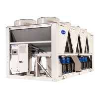
Do you have a question about the Carrier 30RBM 160 and is the answer not in the manual?
Discusses safety precautions for protective devices on the unit.
Covers safe handling and precautions for refrigerants.
Outlines safety measures during unit installation.
Details requirements for unit repairs and modifications.
Mentions pressure equipment recycling.
Discusses safety protocols for maintenance activities.
Covers safety precautions for performing repairs on the unit.
Procedures for inspecting and verifying received equipment.
Guidance on safely lifting and moving the unit.
Instructions for correctly placing the unit for operation.
Provides dimensions and clearance requirements for specific unit sizes.
Details dimensions and clearance requirements for unit sizes 300-400.
Specifies dimensions and clearances for unit sizes 430-520.
Recommendations for arranging multiple units.
Specifies required distances from walls for proper operation.
Lists physical specifications for 30RBM units, sizes 160-520.
Details physical specifications for 30RBP units, sizes 160-520.
Provides electrical data for 30RBM units, sizes 160-520.
Lists electrical specifications for 30RBP units, sizes 160-520.
Specifies short circuit stability current for the units.
Electrical data specific to the hydronic module options.
Notes regarding compressor electrical data.
Details compressor distribution across different circuits.
General notes on electrical data and environmental conditions.
Requirements and guidelines for unit power supply connection.
Explains voltage phase imbalance and its limits.
Provides guidance on selecting appropriate wire sizes.
Details how power cables enter the unit's electrical box.
Instructions for connecting field control wiring.
Information on available power reserves for user connections.
Describes the unit's main power connection and disconnect switch.
Specifies the operational limits for water and air temperatures.
Minimum flow rate for non-hydronic units.
Maximum flow rate for non-hydronic units.
Information on variable flow evaporators for non-hydronic units.
Defines the minimum water volume required for the system.
Specifies the maximum water volume compatible with the unit.
Details water flow rates for heat exchangers with/without hydronic modules.
Curves showing pressure drop vs. water flow rate for heat exchangers.
Precautions and recommendations for water connections.
Schematic diagrams and details of hydronic connections.
Diagrams showing water connections for hydronic modules.
Diagrams showing water connections for non-hydronic units.
Details cavitation protection for hydronic modules.
How water flow rate is detected in the system.
Measures and recommendations for frost protection.
Flow rate control for units without a hydronic module.
Flow rate control for hydronic units with fixed speed pumps.
Flow rate control using pressure differential for variable speed pumps.
Flow rate control using temperature differential for variable speed pumps.
Setting a fixed flow rate for systems with variable speed pumps.
Displays pump pressure and flow rate characteristics.
Information on the available static pressure for the system.
Pre-start-up checks for the thermodynamic system.
Procedures and precautions for unit commissioning.
Key checks for compressors, hydraulics, and refrigerant.
Description and characteristics of the scroll compressors.
Information on compressor oil and its level check.
Details on the micro-channel air-cooled heat exchangers.
Information on fan assemblies, motors, and efficiency.
Description of the electronic expansion valve.
Function and indication of the moisture indicator.
Role and indications of the filter drier.
Details on the brazed plate water heat exchangers.
Information on the refrigerant used (R410A).
Location and function of high-pressure safety pressostats.
Description of variable frequency drives for fan speed control.
Diagrams showing the arrangement of fans per circuit.
Lists fan stages for different unit configurations.
Use of variable speed drives for fan optimization.
Electrical protection for fan motors.
Lists various optional features and their advantages.
Features and usability of the Touch Pilot Control interface.
Components and function of hydronic modules without variable speed pumps.
Details of hydronic modules with variable speed pumps.
Functionality and installation of the partial heat recovery option.
Installation and operation of the heat recovery with desuperheater option.
Installation procedures for the desuperheater option.
Operating limits for the desuperheater option.
Control configuration for the desuperheater option.
Operation of two units in Master/Slave configuration.
Details on medium and low-temperature brine solution options.
Operation and installation of units with variable speed fans.
Functionality and components of the power factor correction option.
Details on the DX Free Cooling option for chilled water production.
Operational procedures for Free Cooling mode.
Operating limits for Cooling and Free Cooling modes.
Simple maintenance tasks performable by the user.
Maintenance requiring specialized expertise in electrical/mechanical systems.
Advanced maintenance requiring specific skills, tools, and manufacturer authorization.
Torque values for tightening electrical connections.
Torque values for main structural fastenings.
Recommendations for cleaning and maintaining air-cooled heat exchangers.
Checks for water heat exchangers, including insulation and connections.
Safety precautions and procedures for working on variable frequency drives.
Procedures for checking and adjusting refrigerant charge.
Properties of R410A refrigerant.
Checks related to the power factor correction system.
Steps for shutting down the unit.
Guidelines for disassembling the unit.
Identification of fluids requiring recovery for treatment.
Listing of materials suitable for recycling.
Procedures for WEEE compliance at end-of-life.
Fields for basic job and equipment information.
Details of the installed equipment.
Fields for compressor model and serial numbers.
Details on air handling equipment manufacturer and model.
Checks for shipping damage and installation readiness.
Checks related to the operation of air handling systems.
Checks for unit start-up readiness and interlocks.
Procedure to check and record voltage imbalance.
Checks for the evaporator water loop, including volume and fluid.
Procedure to measure pressure drop across the evaporator.
Steps for performing the QUICK TEST function.
Procedures for re-entering unit setpoints.
Recording stable temperatures and pressures after start-up.


