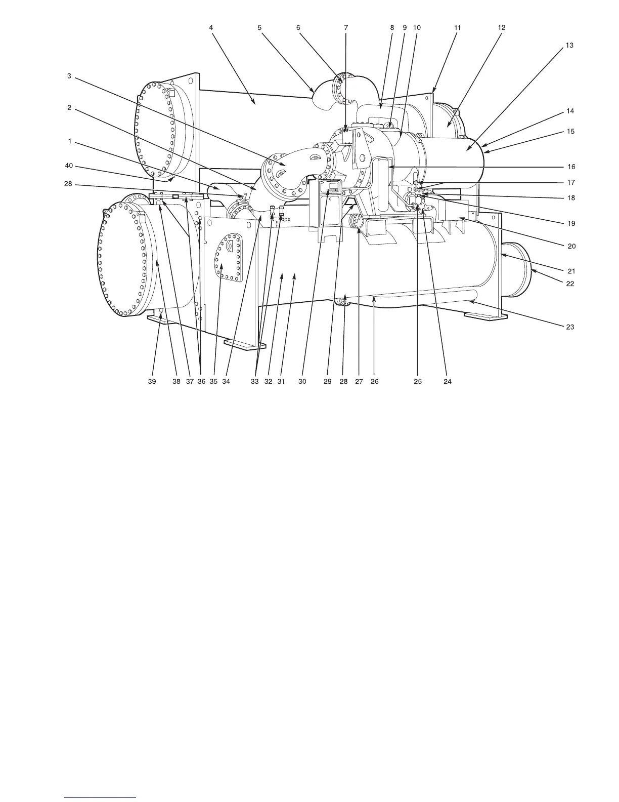
LEGEND
1—Refrigerant Liquid Line to Economizer/Storage Vessel
2—Cooler Suction Pipe
3—Compressor Suction Elbow
4—Condenser
5—Condenser Discharge Pipe
6—Compressor Discharge Elbow
7—Guide Vane Actuator
8—Economizer Gas Line to Compressor
9—Gear Inspection Cover
10 — 2-Stage Hermetic Compressor
11 — Condenser Waterbox Vent (Not Shown)
12 — Condenser Marine Waterbox
13 — Hermetic Compressor Motor
14 — Compressor Motor Terminal Box (Not Shown)
15 — Motor Sight Glass (Not Shown)
16 — Oil Filter
17 — Oil Level Sight Glasses (2)
18 — Cooler Relief Valves (Not Shown)
19 — Oil Heater (Not Shown)
20 — Auxiliary Power Panel (Field Wiring Terminals)
21 — Pumpdown Unit (Not Shown)
22 — Low-Side Float Box Cover
23 — Refrigerant Liquid Line to Cooler
24 — Oil Drain and Charging Valve
25 — Oil Pump
26 — Refrigerant Charging/Service Valve 10
(Not Shown)
27 — Oil Cooler
28 — Isolation Valves (Not Shown)
29 — Refrigerant Filter Drier
30 — Local Interface Display Control Panel
31 — Economizer/Storage Vessel
32 — Rigging Guide (Not Shown)
33 — Economizer/Storage Vessel Relief Valves
34 — Cooler
35 — High-Side Float Box Cover
36 — Take-Apart Connections
37 — Cooler Waterbox Vent
38 — Cooler Marine Waterbox
39 — Cooler Waterbox Drain
40 — Condenser Waterbox Drain
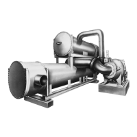
Fig.3—Typical 19EX Installation
7