7
REFRIGERATION CYCLE
The compressor continuously draws refrigerant vapor from
the cooler at a rate set by the amount of guide vane opening or
compressor speed. As the compressor suction reduces the
pressure in the cooler, the remaining refrigerant boils at a fairly
low temperature (typically 38 to 42 F [3 to 6 C]). The energy
required for boiling is obtained from the water flowing through
the cooler tubes. With heat energy removed, the water becomes
cold enough to use in an air conditioning circuit or for process
liquid cooling.
After taking heat from the water, the refrigerant vapor is
compressed. Compression adds still more heat energy, and the
refrigerant is quite warm (typically 98 to 102 F [37 to 40 C])
when it is discharged from the compressor into the condenser.
Relatively cool (typically 65 to 90 F [18 to 32 C]) water
flowing into the condenser tubes removes heat from the refrig-
erant and the vapor condenses to liquid.
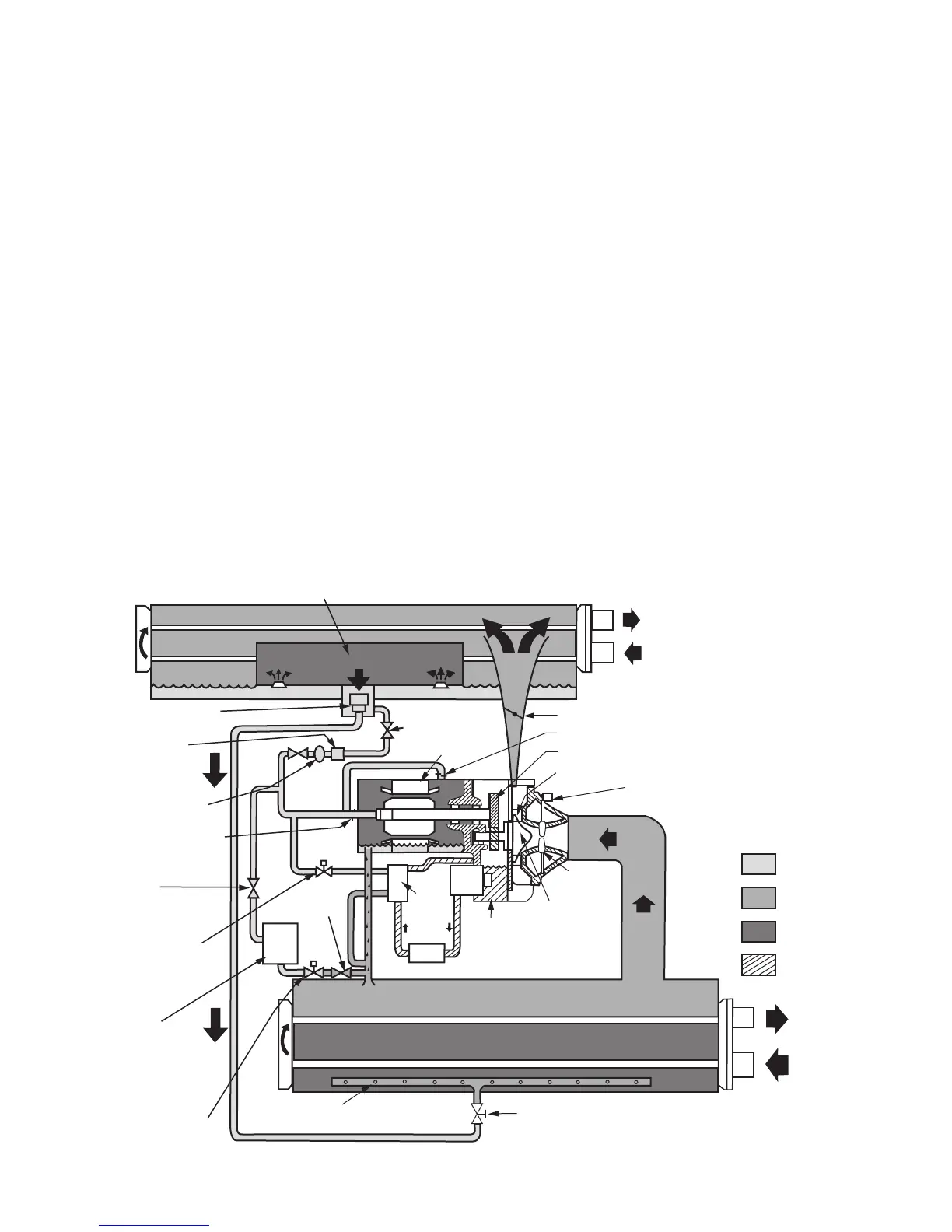
The liquid refrigerant passes through orifices into the
FLASC (Flash Subcooler) chamber (Fig. 3). Since the FLASC
chamber is at a lower pressure, part of the liquid refrigerant
flashes to vapor, thereby cooling the remaining liquid. The
FLASC vapor is recondensed on the tubes which are cooled by
entering condenser water. The liquid drains into a float cham-
ber between the FLASC chamber and cooler. Here, a float
valve forms a liquid seal to keep FLASC chamber vapor from
entering the cooler. When liquid refrigerant passes through the
valve, some of it flashes to vapor in the reduced pressure on the
cooler side. In flashing, it removes heat from the remaining
liquid. The refrigerant is now at a temperature and pressure at
which the cycle began.
MOTOR AND LUBRICATING OIL
COOLING CYCLE
The motor and the lubricating oil are cooled by liquid re-
frigerant taken from the bottom of the condenser vessel
(Fig. 3). Refrigerant flow is maintained by the pressure differ-
ential that exists due to compressor operation. After the refrig-
erant flows past an isolation valve, an in-line filter, and a sight
glass/moisture indicator, the flow is split between the motor
cooling and oil cooling systems.
Flow to the motor cooling system passes through an orifice
and into the motor. Once past the orifice, the refrigerant is
directed over the motor by a spray nozzle. The refrigerant
collects in the bottom of the motor casing and is then drained
back into the cooler through the motor refrigerant drain line.
An orifice (in the motor shell) maintains a higher pressure in
the motor shell than in the cooler. The motor is protected by a
temperature sensor imbedded in the stator windings. An
increase in motor winding temperature past the motor override
set point overrides the temperature capacity control to hold,
and if the motor temperature rises 10° F (5.5° C) above this set
point, closes the inlet guide vanes. If the temperature rises
above the safety limit, the compressor shuts down.
Refrigerant that flows to the oil cooling system is regulated
by thermostatic expansion valves (TXVs). The TXVs regulate
flow into the oil/refrigerant plate and frame-type heat exchang-
er (the oil cooler in Fig. 3). The expansion valve bulbs control
oil temperature to the bearings. The refrigerant leaving the oil
cooler heat exchanger returns to the chiller cooler.
UNIT
MOUNTED
VFD
(VARIABLE
FREQUENCY
DRIVE)
HEAT
EXCHANGER
THERMOSTATIC
EXPANSION
VALVE
(TXV)
ORIFICE
FITTING
MOISTURE/
FLOW
INDICATOR
FILTER
DRIER
FLOAT VALVE
CHAMBER
REFRIGERANT
COOLING
ISOLATION VALVE
MOTOR
CONDENSER ISOLATION VALVE (OPTION)
ORIFICE FITTING
TRANSMISSION
DIFFUSER
GUIDE VANE
MOTOR
GUIDE
VANES
IMPELLER
FLASC CHAMBER
CONDENSER
CONDENSER
WATER
STATOR
ROTOR
OIL
PUMP
COMPRESSOR
COOLER ISOLATION
VALVE (OPTION)
DISTRIBUTION
PIPE
REFRIGERANT
LIQUID
REFRIGERANT
VAPOR
REFRIGERANT
LIQUID/VAPOR
OIL
CHILLED
WATER
OIL
COOLER
OIL
FILTER
VFD COOLING
SOLENOID
VFD
COOLING
ISOLATION
VALVE
VFD
COOLING
ISOLATION
VALVE
Fig. 3 — Refrigerant Motor Cooling and Oil Cooling Cycles
a19-1601

 Loading...


