9
STARTING EQUIPMENT
All 19XRV units are equipped with a VFD to operate the
centrifugal hermetic compressor motor. A power panel controls
the oil pump, and various auxiliary equipment. The VFD and
power panel are the main field wiring interfaces for the install-
ing contractor. The VFD is mounted directly on the chiller.
Three separate circuit breakers are inside the VFD. Circuit
breaker CB1 is the VFD circuit breaker. The disconnect switch
on the VFD front cover is connected to this breaker. Circuit
breaker CB1 supplies power to the VFD.
Circuit breaker CB2 supplies 115-v power to the oil pump
control panel, oil heater, and portions of the VFD controls.
Unit-Mounted VFD — The 19XRV chiller is equipped
with a variable frequency drive motor controller mounted on
the condenser. See Fig. 5-7. This VFD is used with low voltage
motors between 380 and 460 vac. It reduces the starting current
inrush by controlling the voltage and frequency to the compres-
sor motor. Once the motor has accelerated to minimum speed,
the PIC III modulates the compressor speed and guide vane
position to control chilled water temperature. The VFD is
further explained in the Controls section and Troubleshooting
Guide section, pages 14 and 82.
Operational parameters and fault codes are displayed rela-
tive to the drive. Refer to specific drive literature along with
troubleshooting sections. The display is also the interface for
entering specific chiller operational parameters. These parame-
ters have been preprogrammed at the factory. An adhesive
backed label on the inside of the drive has been provided for
verification of the specific job parameters. See Initial Start-Up
Checklist section for details.
The main circuit breaker (CB1) on the front of the VFD
disconnects the main VFD current only. Power is still ener-
gized for the other circuits. Two more circuit breakers
inside the VFD must be turned off to disconnect power to
the oil pump, PIC III controls, and oil heater.
Do not touch the power wiring or motor terminals while
voltage is present, or serious injury will result.
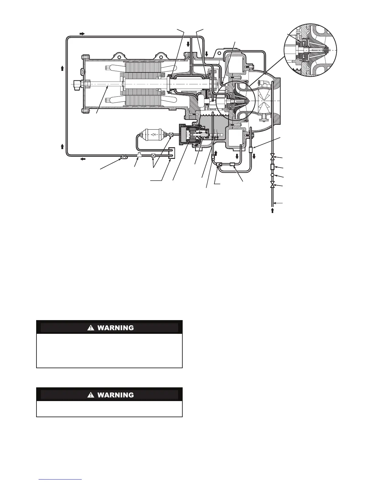
ISOLATION
VALVE
SIGHT
GLASS
FILTER
ISOLATION
VALVE
FILTEREDUCTOR
OIL
PUMP
TXV BULB PRESSURE
TRANSDUCER
ISOLATION
VALVES
OIL
COOLER
OIL PUMP
MOTOR
OIL
HEATER
MOTOR
COOLING LINE
LABYRINTH
GAS LINE
FWD MOTOR
BEARING
OIL SUPPLY TO
FORWARD HIGH
SPEED BEARING
SIGHT
GLASS
OIL SKIMMER
LINE
FLOW
OIL
FILTER
REAR MOTOR
BEARING
STRAINER
Fig. 4 — Lubrication System
a19-1741

 Loading...


