Al1140
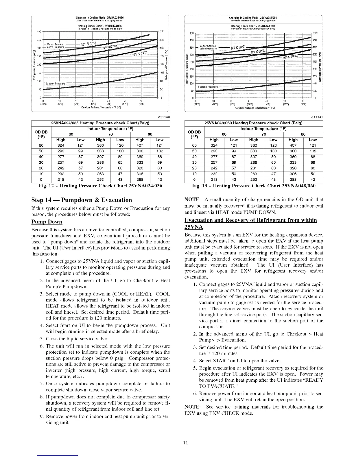
25VNA024/036 Heating Pressure check Cha_ (Psig)
Indoor Temperature (°F)
OD DB
60 70 80
(°F)
High Low High Low High Low
60 324 121 360 120 407 121
50 293 99 333 100 300 102
40 277 87 307 80 360 88
30 257 69 288 65 333 69
20 242 57 281 60 320 60
10 232 50 263 47 306 50
0 218 42 253 43 288 42
Fig. 12 - Heating Pressure Check Chart 25VNA024/036
Step 14 -- Pumpdown & Evacuation
If this system requires either a Pump Down or Evacuation for any
reason, the procedures below must be followed:
Pump Down
Because this system has aninverter controlled, compressor, suction
pressure transducer and EXV, conventional procedure cannot be
used to "pump down" and isolate the refrigerant into the outdoor
unit. The UI (User Interface) has provisions to assist in performing
this function.
1. Connect gages to 25VNA liquid and vapor or suction capil-
lary service ports to monitor operating pressures during and
at completion of the procedure.
2. In the advanced menu of the UI, go to Checkout > Heat
Pump> Pumpdown
3. Select mode to pump down in (COOL or HEAT), COOL
mode allows refrigerant to be isolated in outdoor unit.
HEAT mode allows the refrigerant to be isolated in indoor
coil and lineset. Set desired time period. Default time peri-
od for the procedure is 120 minutes.
4. Select Start on UI to begin the pumpdown process. Unit
will begin running in selected mode after a brief delay.
5. Close the liquid service valve.
6. The unit will run in selected mode with the low pressure
protection set to indicate pumpdown is complete when the
suction pressure drops below 0 psig. Compressor protec-
tions are still active to prevent damage to the compressor or
inverter (high pressure, high current, high torque, scroll
temperature, etc.).
7. Once system indicates pumpdown complete or failure to
complete shutdown, close vapor service valve.
8. If pumpdown does not complete due to compressor safety
shutdown, a recovery system will be required to remove fi-
nal quantity of refrigerant from indoor coil and line set.
9. Remove power from indoor and heat pump unit prior to ser-
vicing unit.
ChargingIn Cooling M0de- 25VNA048/060
See user interface set #1 Charging Mode
Heating Check Chart - 25VNA048/060
For use in Heating Charging Modeorgy
Al1141
25VNA048/060 Heating Pressure check Chaff (Psig)
Indoor Temperature (°F)
OD DB
60 70 80
(°F)
High Low High Low High Low
60 324 121 360 120 407 121
50 293 99 333 100 380 102
40 277 87 307 80 360 88
30 257 69 288 65 333 69
20 242 57 281 60 320 60
10 232 50 263 47 306 50
0 218 42 253 43 288 42
Fig. 13 - Heating Pressure Check Chart 25VNA048/060
NOTE: A small quantity of charge remains in the OD unit that
must be manually recovered if isolating refrigerant to indoor coil
and lineset via HEAT mode PUMP DOWN.
Evacuation and Recovery of Refrigerant from within
25VNA
Because this system has an EXV for the heating expansion device,
additional steps must be taken to open the EXV if the heat pump
unit must be evacuated for service reasons. If the EXV is not open
when pulling a vacuum or recovering refrigerant from the heat
pump unit, extended evacuation time may be required and/or
inadequate vacuum obtained. The UI (User Interface) has
provisions to open the EXV for refrigerant recovery and/or
evacuation.
1. Connect gages to 25VNA liquid and vapor or suction capil-
lary service ports to monitor operating pressures during and
at completion of the procedure. Attach recovery system or
vacuum pump to gage set as needed for the service proced-
ure. The service valves must be open to evacuate the unit
through the line set service ports. The suction capillary ser-
vice port is a direct connection to the suction port of the
compressor.
2. In the advanced menu of the UI, go to Checkout > Heat
Pump> > Evacuation.
3. Set desired time period. Default time period for the proced-
ure is 120 minutes.
4. Select START on UI to open the valve.
5. Begin evacuation or refrigerant recovery as required for the
procedure after UI indicates the EXV is open. Power may
be removed from heat pump after the UI indicates "READY
TO EVACUATE."
6. Remove power from indoor and heat pump unit prior to ser-
vicing unit. The EXV will retain the open position.
NOTE: See service training materials for troubleshooting the
EXV using EXV CHECK mode.
11

 Loading...