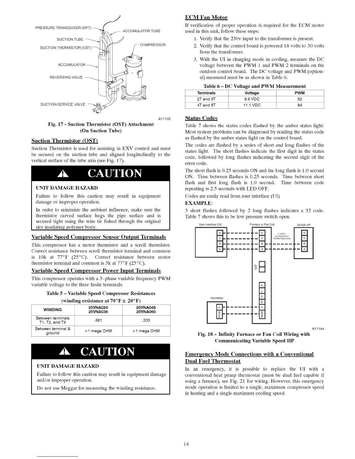
PRESSURETRANSDUCER(SPT)
ACCUMULATOR TUBE
SUCTION THERMISTOR
REVERSING VALVE
SUCTION SERVICE VALVE
Al1103
Fig. 17 - Suction Thermistor (OST) Attachment
(On Suction Tube)
Suction Thermistor (OST)
Suction Thernfistor is used for assisting in EXV control and must
be secured on the suction tube and aligned longitudinally to the
vertical surface of the tube axis (see Fig. 17).
UNIT DAMAGE HAZARD
Failure to follow this caution may result in equipment
damage or improper operation.
In order to nfininfize the ambient influence, make sure the
thernfistor curved surface hugs the pipe surface and is
secured tight using the wire tie fished through the original
slot insulating polymer body.
Variable Speed Compressor Sensor Output Terminals
This compressor has a motor thermistor and a scroll thermistor.
Correct resistance between scroll thermistor terminal and common
is 10k at 77°F (25°C). Correct resistance between motor
thermistor terminal and common is 5k at 77 °F (25 o C).
Variable Speed Compressor Power Input Terminals
This compressor operates with a 3-phase variable frequency PWM
variable voltage to the three fusite terminals.
Table 5 - Variable Speed Compressor Resistances
(winding resistance at 70°F 4- 20°F)
25VNA024 25VNA048
WINDING 25VNA036 25VNA060
Betweenterminals
T1, T2, and T3 .681 .203
Between terminal &
ground >1 mega OHM >1 mega OHM
[]NIT DAMAGE HAZARD
Failure to follow this caution may result in equipment damage
and/or improper operation.
Do not use Meggar for measuring the winding resistance.
ECM Fan Motor
If verification of proper operation is required for the ECM motor
used in this unit, follow these steps:
1. Verify that the 230v input to the transformer is present.
2. Verify that the control board is powered 18 volts to 30 volts
from the transformer.
3. With the UI in charging mode in cooling, measure the DC
voltage between the PWM 1 and PWM 2 terminals on the
outdoor control board. The DC voltage and PWM (option-
al) measured nmst be as shown in Table 6.
Table 6 - DC Voltage and PWM Measurement
Terminals Voltage PWM
2T and 3T 8.9 VDC 52
4T and 5T 11.1 VDC 84
Status Codes
Table 7 shows the status codes flashed by the amber status light.
Most system problems can be diagnosed by reading the status code
as flashed by the amber status light on the control board.
The codes are flashed by a series of short and long flashes of the
status light. The short flashes indicate the first digit in the status
code, followed by long flashes indicating the second digit of the
error code.
The short flash is 0.25 seconds ON and the long flash is 1.0 second
ON. Time between flashes is 0.25 seconds. Time between short
flash and first long flash is 1.0 second. Time between code
repeating is 2.5 seconds with LED OFF.
Codes are easily read from user interface (UI)
EXAMPLE:
3 short flashes followed by 2 long flashes indicates a 32 code.
Table 7 shows this to be low pressure switch open.
User Interface (U[) Furnace or Fan Coil
,m_Hm
,m I t_ I,,= =
....... i A _='=
Humidifier
25VNA HP
CandD
t,===,l
,_11© i
Fig. 18 - Infinity Furnace or Fan Coil Wiring with
Communicating Variable Speed HP
Al1144
Emergency Mode Connections with a Conventional
Dual Fuel Thermostat
In an emergency, it is possible to replace the UI with a
conventional heat pump thermostat (nmst be dual fuel capable if
using a furnace), see Fig. 21 for wiring. However, this emergency
mode operation is linfited to a single, maximum compressor speed
in heating and a single maximum cooling speed.
14

 Loading...