11
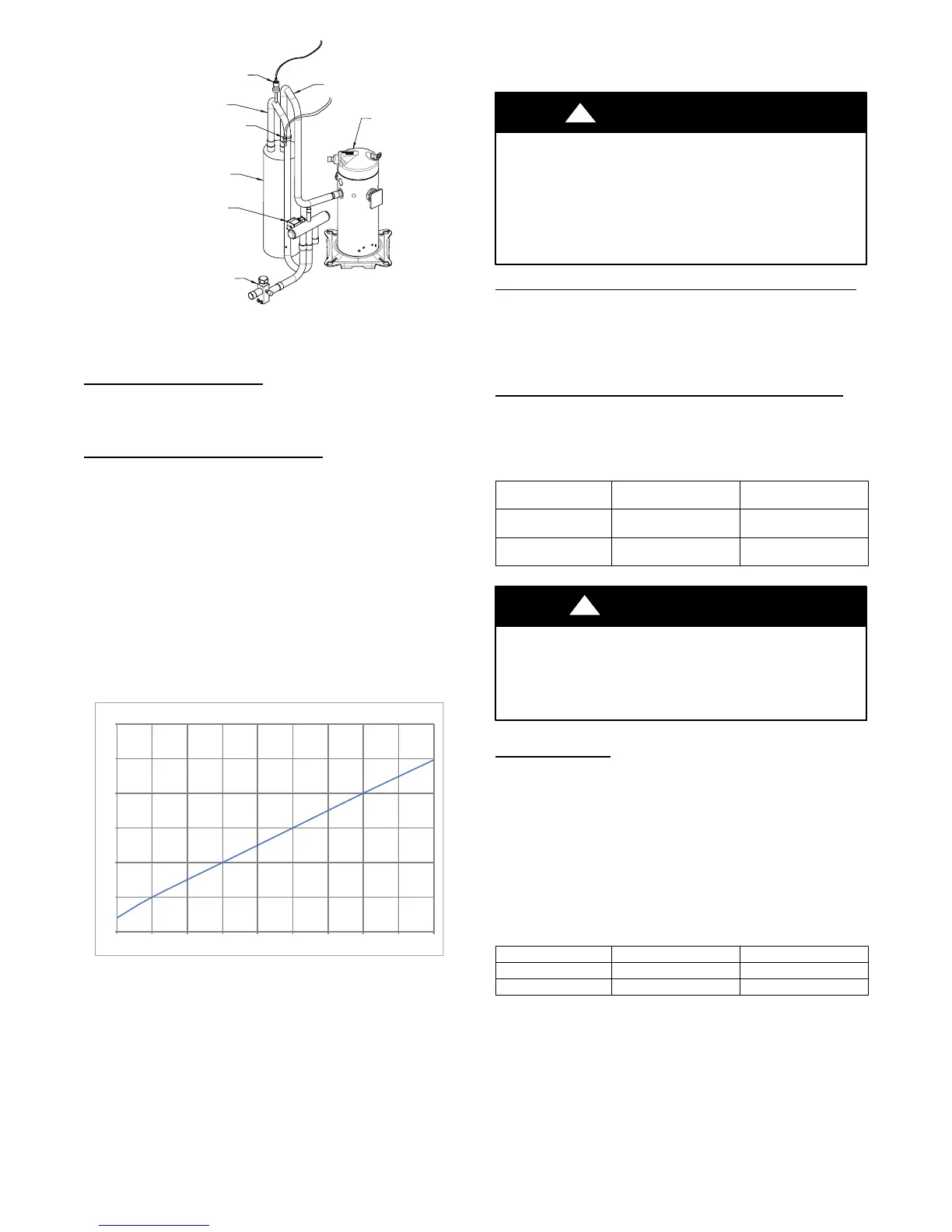
REVERSING VALVE
ACCUMULATOR
SUCTION TUBE
SUCTION THERMISTOR (OST)
SUCTION SERVICE VALVE
ACCUMULATOR TUBE
COMPRESSOR
PRESSURE TRANSDUCER (SPT)
A11103
Fig. 10 – Suction Thermistor (OST) Attachment
(On Suction Tube)
Suction Thermistor (OST)
Suction Thermistor is used for assisting in EXV control and must
be secured on the suction tube and aligned longitudinally to the
vertical surface of the tube axis (see Fig. 10).
Suction Pressure Transducer (SPT)
If the accuracy of the transducer is questioned, the technician can
check it while it is attached to the VSHP board. Connect a gage
manifold to the suction valve gage port fitting.
At the VSHP board, with the wire harness receptacle exposing a
portion of the three pins on the VSHP board, a DC voltmeter can
read the DC voltage between ground and supply (input) terminal.
Ensure that the input voltage is 5 VDC. Next, read the DC voltage
across the ground and output terminal. Record the output voltage.
The suction pressure that the pressure transducer is reading can be
calculated by taking the output voltage and subtracting 0.5 from it
then taking that difference and multiplying it by 50. Pressure
(psig) = 50.0 x (DCV out -- 0.5). For example, if the measured
voltage is 3.0 VDC: 50 X (3.0 -- 0.5) -- 50 X 2.5 = 125 psig. See
Fig. 11.
0
1
2
3
4
5
6
0 25 50 75 100 125 150 175 200 225
Pressure - Sealed Gauge (psi)
A12035
Fig. 11 – Suction Pressure Transducer (SPT)
Output Funtion Graph
This can then be compared to the actual suction pressure from the
gage manifold.
In the event of a low pressure trip or low pressure lockout , check
the refrigerant for an under charge. If the charge is found to be
correct, check for low indoor airflow in cooling and the outdoor
fan for proper operation in heating and outdoor coil in heating for
airflow restrictions. Keep in mind that the outdoor fan motor may
run normally until it heats up.
Cool: PSUCT < 55 psig (for 3 minutes)
Heat: PSUCT < 23 psig (for 3 minutes)
PSUCT < 13 psig (instantaneous)
CAUTION
!
UNIT DAMAGE HAZARD
Failure to follow this caution may result in equipment
damage or improper operation.
In order to minimize the ambient influence, make sure the
thermistor curved surface hugs the pipe surface and is
secured tight using the wire tie fished through the original
slot insulating polymer body.
Variable Speed Compressor Sensor Output Terminals
This compressor has a motor thermistor and a scroll thermistor.
Correct resistance between scroll thermistor terminal and common
is 10k at 77_F(25_C). Correct resistance between motor
thermistor terminal and common is 5k at 77_F(25_C). See Table
7.
Variable Speed Compressor Power Input Terminals
This compressor operates with a 3--phase variable frequency PWM
variable voltage to the three fusite terminals.
Table 3—Variable Speed Compressor Resistances
(winding resistance at 70_F 20_F)
WINDING
25VNA024
25VNA036
25VNA048
25VNA060
Between terminals
T1, T2, and T3
.681 .203
Between terminal &
ground
>1 mega OHM >1 mega OHM
UNIT DAMAGE HAZARD
Failure to follow this caution may result in equipment damage
and/or improper operation.
Do not use Meggar for measuring the winding resistance.
CAUTION
!
ECM Fan Motor
If verification of proper operation is required for the ECM motor
used in this unit, follow these steps:
1. Verify that the 230v input to the transformer is present.
2. Verify that the control board is powered 18 volts to 30 volts
from the transformer.
3. With the UI in charging mode in cooling, measure the DC
voltage between the PWM 1 and PWM 2 terminals on the
outdoor control board. The DC voltage and PWM (option-
al) measured must be as shown in Table 4.
Table 4—DC Voltage and PWM Measurement
Unit Size Voltage PWM
024, 036 8.9 VDC 52
048, 060 11.1 VDC 84
 Loading...