37MARAQ: Installation Instructions
Manufacturer reserves the right to change, at any time, specifications and designs without notice and without obligations.
20
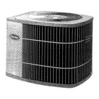
Step 3 - Anchor the Outdoor Unit
• The outdoor unit can be anchored to the ground or to a wall-mounted bracket with bolt (M10). Prepare the installation base of the unit according to
Figure 10.
• Table 9 lists outdoor unit sizes and the distance between their mounting feet. Prepare the installation base of the unit according to the dimensions
listed in Table 9.
Fig. 10 — Anchor Outdoor unit
Table 9 — Dimensions
If you install the unit on the ground or on a concrete mounting
platform, perform the following steps.
1. Mark the positions for four expansion bolts based on the dimensions
chart.
2. Pre-drill holes for expansion bolts.
3. Place a nut on the end of each expansion bolt.
4. Hammer expansion bolts into the pre-drilled holes.
5. Remove the nuts from expansion bolts, and place the outdoor unit on
bolts.
6. Put a washer on each expansion bolt, then replace the nuts.
7. Use a wrench to tighten each nut until snug.
If you install the unit on a wall-mounted bracket, perform the
following steps.
1. Mark the position of bracket holes based on the dimensions chart.
2. Pre-drill the holes for the expansion bolts.
3. Place a washer and nut on the end of each expansion bolt.
4. Thread expansion bolts through holes in the mounting brackets, put
mounting brackets in position, and hammer the expansion bolts into the
wall.
5. Ensure the mounting brackets are level.
6. Carefully lift unit and place its mounting feet on brackets.
7. Bolt the unit firmly to the brackets.
8. If allowed, install the unit with rubber gaskets to reduce vibrations and
noise.
When drilling into concrete, eye protection is recommended at all
times.
WA R N I N G
OUTDOOR UNIT DIMENSIONS
W X H X D
MOUNTING DIMENSIONS
DISTANCE A DISTANCE B
30.1inx 21.8inx 11.9in (765mmx555mmx303mm) 17.8in (452mm) 11.3in (286mm)
35.0inx 26.5inx 13.5in (890mmx673mmx342mm) 26.1in (663mm) 13.9in (354mm)
37.2inx 31.9inx 16.1in (946mmx810mmx410mm) 26.5in (673mm) 15.9in (403mm)
W
H
Top view Front view
D
A
B
Air inlet
Air inlet
Air outlet
Ensure the wall is made of solid brick, concrete, or of similarly
strong material. The wall must be able to support at least four times
the weight of the unit.
CAUTION

 Loading...


