9
38AW-
Electrical connections (Fig. 10, 11, 12)
Connection to units 80AWX, 80AWH: see g. 11
Hydronic module (Indoor unit)
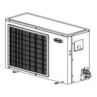
Outdoor unit
Circuit breaker *
Mains supply connecting cable (eld wiring)
Interconnecting cable (outdoor)
Interconnecting cable (indoor)
Earth
L Live power supply
N Neutral power supply
1 - 2 - 3 Connection indoor/outdoor unit
Wiring size - g. 11 B.
Cable type and size (-): H07RN-F 4x1 mm
2
Cable type and size (): H07RN-F 3x2,5 mm
2
Connection to units 80AW1, 80AW2, 80AWT: see g. 12
Hydronic module (Indoor unit)
Outdoor unit
Circuit breaker
Mains supply connecting cable (eld wiring)
Interconnecting cable (outdoor)
Interconnecting cable (indoor)
Earth
L Live power supply
N Neutral power supply
1 - 2 - 3 Connection indoor/outdoor unit
Wiring size - g. 12 B.
Cable type and size (-): H07RN-F 3x1 mm
2
Cable type and size (): H07RN-F 3x2,5 mm
2
Remove the front panel, the electric parts appear at the
front side.
The power supply cables can be inserted into the pipe
holes. Enlarge the pipe holes if they are too small.
Be sure to x the power cable and indoor/outdoor
connecting cable with bundling band sold on the market
so that they do not make contact with the compressor and
the hot pipes.
To ensure good tensile strength, the electric cables must be
fastened using the cable-holder on the plate (See g. 10).
Size 50 65 90 115
Maximum running current A 12 A 14 A 22 A 22,8 A
Nominal single-phase voltage
50 Hz
230 V
Operating voltage limits min 198V ÷ max 264V
Also check the supply voltage and frequency of the indoor unit.
All eld electrical connections are the responsibility of the installer.
Please refer to the hydronic module manual.
WARNING
Make refrigerant connections before electrical connections.
Make ground connection prior to any other electrical connections.
IMPORTANT
The ground wire for the indoor unit
outdoor unit connection cable must be
clamped to a soft copper tin-plated eyelet
terminal with M4 screw hole.
English

 Loading...


