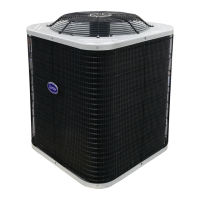
Compressor Crankcase Heater — A crankcase heater is required if refrigerant tubing is longer than 80 ft. (24.38 m).
When equipped with a crankcase heater, energize heater a minimum of 24 hours before starting unit. To energize
heater only, set thermostat to OFF mode and close electrical disconnect to outdoor unit.
Install Electrical Accessories — Refer to individual instructions packaged with kits or accessories when installing.
Start-Up
Preliminary Checks
1. Check that all the internal wiring connections are tight and that barriers, covers and panels are in place.
2. Make certain field electrical power source agrees with unit nameplate and rating.
3. Open all service valves.
Leak Test — Field piping and fan coil must be leak tested by pressure method described in Carrier Standard Service
Techniques Manual, Chapter 1, Section 1-6.
Evacuate and Dehydrate— Field piping and fan coil must be evacuated and dehydrated by either of the methods
described in Carrier Standard Service Techniques Manual, Chapter 1, Section 1-7.
Charge System — Release factory charge into system by opening (back seating) liquid and suction line service
valves. Add charge amount as required for the total system. Refer to separate indoor unit installation instructions for
the required total system charge when connected to the indoor unit.
Percentage decrease in capacity due to Maximum Line Lengths, Please refer to Long Line Guideline.
To Start Unit
NOTE: Please use the Pre-startup and Startup included with the fan coil units for correct start-up procedures. Be
sure that field disconnect is closed. Set room thermostat below ambient temperature. Operate unit for 15 minutes,
then check system refrigerant charge.
Sequence Of Operation
Turn on power to indoor and outdoor units. Transformer is energized. On a call for cooling, thermostat makes circuits
Y1-Y2 and L-N. Three phase models are equipped with a phase monitor to detect if the incoming power is correctly
phased for compressor operation. If the phasing is correct, circuit Y1-Y2 energizes contactor, starting outdoor fan
motor and compressor circuit. L-N energizes indoor unit blower relay, starting indoor blower motor on high speed.
NOTE: If the phasing is incorrect, the contactor will not be energized. To correct the phasing, interchange any two of
the three power connections on the field side.
When thermostat is satisfied, its contacts open, de-energizing contactor and blower relay. Compressor and motors
stop.
Fig. 7 Three Phase Monitor Control
Before performing service or maintenance, be sure the indoor unit main power switch is off and indoor blower
has completely stopped. Do not supply power to unit with compressor terminal box cover removed. Failure to
do so may result in electrical shock or injury from rotating fan blades.
• 3-phase scroll compressors are rotation sensitive.
• A red LED on phase monitor indicates reverse rotation.
• This will not allow contactor to be energized.
• Disconnect power to unit and interchange 2 field wiring leads on

 Loading...