5
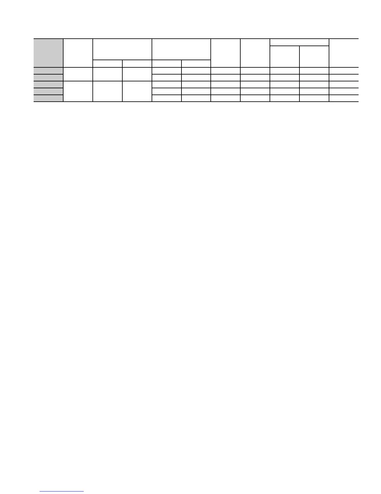
Electrical data
* Permissible limits of the voltage range at which unit will operate satisfactorily. Operation outside these limits may result in unit failure.
† Time-delay fuse.
‡ Length shown is as measured 1 way along wire path between the unit and service panel for a voltage drop not to exceed 2%.
** If wire is applied at ambient greater than 30°C (86°F), consult Table 310-16 of the NEC (ANSI/NFPA 70).
The ampacity of nonmetallic-sheathed cable (NM), trade name ROMEX, shall be that of 60°C (140°F) conductors, per the NEC (ANSI/NFPA 70)
Article 336-26. If other than uncoated (non-plated), 60 or 75°C (140 or 167°F) insulation, copper wire (solid wire for 10 AWG and smaller, stranded
wire for larger than 10 AWG) is used, consult applicable tables of the NEC (ANSI/NFPA 70).
FLA
— Full Load Amps
LRA
— Locked Rotor Amps
MCA
— Minimum Circuit Amps
RLA
— Rated Load Amps
NOTES:
1. Control circuit is 24v on all units and requires external power source.
2. Copper wire must be used from service disconnect to unit.
3. All motors/compressors contain internal overload protection.
UNIT
SIZE V/PH
OPER VOLTS* COMPRESSOR
FAN
FLA MCA
FIELD WIRE SIZE
MAX FUSE†
OR
CKT BKR
AMPS
Min
Wire
Size
60°C/75°C**
Max
Length
(m)
60°C/75°C‡
Max Min LRA RLA
024-71
230-1 253 207
68.0 11.6 0.65 15.2 14/14 16.2/15.2 25
036-71
94.0 17.7 0.65 22.8 12/12 16.8/15.8 35
036-91
400-3 440 360
42.0 6.4 0.40 8.4 14/14 61.6/58.5 15
048-91
63.0 7.9 0.70 10.6 14/14 50.3/47.9 15
060-91
74.0 9.0 0.70 12.0 14/14 46.3/43.9 20