11
UNIT MOUNTING (INDOOR)
Mounting Bracket – The fan coil units are furnished with
mounting bracket to hang the unit.
Support – Adequate support must be provided to handle the
weight of all fan coils. Refer to the Physical Data section for
weights, and the base unit dimensional drawings.
Unit Leveling – For reliable operation, units should be level in all
planes.
Clearances – Minimum clearance as shown in Fig. 2.
Unit location – Select a location which will provide the best air
circulation for the room. These units should be positioned as high
as possible on the wall for the best air circulation. The unit return
and discharge should not be obstructed by furniture, curtains, or
anything which may cause the unit to short cycle or air to recycle.
Place the unit in the middle of the selected wall (if possible). Use
an outside wall, if available, to make piping easier, and place the
unit so it faces the normal location of room occupants.
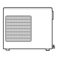
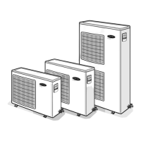
UNIT MOUNTING (OUTDOOR)
Support – A location which can bear the weight of outdoor unit.
Refer to the Physical Data section for weights, and base
dimensional drawings.
Unit Leveling – For reliable operation, units should be level in all
planes.
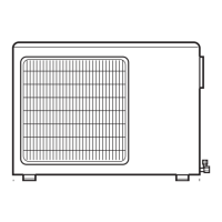
Clearances – Minimum clearances, as shown in Fig. 3, must be
provided for airflow. The outdoor units are designed for free--blow
applications. Air inlets and outlets should not be restricted.
Unit location – A location which is convenient to installation and
not exposed to strong wind.
SYSTEM OPERATING CONDITIONS
Cooling operating range:
Maximum Minimum
DB
_F(_C)
WB
_F(_C)
DB
_F(_C)
WB
_F(_C)
Outdoor Unit
115
(46.1)
---
55
(12.8)
---
Indoor Unit
95
(35)
---
55
(12.8)
---
Heating operating range:
Maximum Minimum
DB
_F(_C)
WB
_F(_C)
DB
_F(_C)
WB
_F(_C)
Outdoor Unit
75
(23.9)
---
14
( --- 1 0 )
---
Indoor Unit
80
(26.7)
---
55
(12.8)
---
METERING DEVICES
The outdoor unit has multiple electronic expansion valves to
manage the refrigerant flow to the different indoor fan coils
connected to that unit.
REFRIGERANT LINES
Routing – Refrigerant lines can be routed in any of the four
directions shown in Fig. 4.
1
Right Exit
2
Right Rear Exit
3LeftExit
4
Left Rear Exit
(a)
(b)
As viewed from front
Fig. 4 – Refrigerant Line Routing
A08281
General Guidelines:
1. The 38GXM units are shipped with full charge of R--410A
refrigerant. All charges, line sizing, and capacities are based
on runs of 16 ft (9.1 m) for units sizes 18 and 24K, and 30
ft. (9.1 m.) for size 30K. For runs over the previous limits,
consult long line section for charge adjustments.
2. Refrigerant lines should not be buried in the ground. If it is
necessary to bury the lines, not more than 36 inches (914
mm) should be buried. Provide a minimum of 6 inch (152
mm) vertical rise to service valves to prevent refrigerant
migration.
3. Both lines must be insulated. Use a minimum of ½-- i n c h
(12.7 mm) thick insulation. Closed--cell insulation is
recommended in all long--line applications.
4. Special consideration should be given to isolating
interconnecting tubing from the building structure. Isolate
the tubing so that vibration or noise is not transmitted into
the structure.
Long Line Applications:
1. No change in line sizing is required.
2. For line lengths above the mentioned in the general
guidelines section, add 0.24 oz. per additional foot of piping
up to the maximum allowed.
38/40GXM
 Loading...