LEGEND AND NOTES FOR FIG. 24 AND 25
AGING — For the Burn-In Test
(short terminals)
AS — Assembly
C—Contactor
CAP — Capacitor
CH — Crankcase Heater
CLO — Compressor Lockout
CN — Connector
COMP — Compressor
CT — Current Transformer
DFB — Defrost Board
DFT — Defrost Thermostat
EQUIP GND — Equipment Ground
FMC — Fan Motor Capacitor
GND — Ground
HA — Home Automation
HPS — High-Pressure Switch
IDC TH — Indoor-Coil Thermistor
IDFM — Indoor Fan Motor
JEM-A — Japan Electric Manufacturing
Industry Association
LLPS — Liquid Low Pressure Switch
LPS — Low-Pressure Switch
OAC TH — Outdoor Coil Thermistor
ODA TH — Outdoor-Air Thermistor
ODC TH — Outdoor-Coil Thermistor
OFM — Outdoor Fan Motor
OFR — Outdoor Fan Relay
OL — Overload
PCB — Printed Circuit Board
RA TH — Return Air Thermistor
RC — Resistor Capacitor
RCV — Receiver
RVS — Reversing Valve Solenoid
SC — Start Capacitor
SR — Start Relay
STM — Step Motor
TB — Terminal Block
TRAN — Transformer
U—Unloader
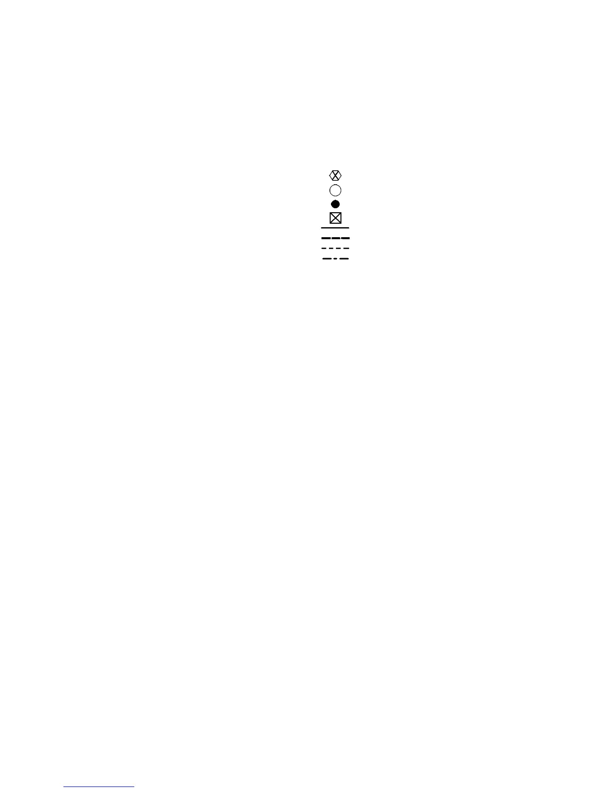
Terminal (Marked)
Terminal (Unmarked)
Splice
Terminal Block
Factory Wiring
Field Control Wiring
Field Power Wiring
Accessory or Optional Wiring
1. If any of the original wire furnished must be replaced, it must be
replaced with type 90 C wire or its equivalent.
2. Wire in accordance with National Electrical Code (NEC) and local
codes.
3. The CLO locks out the compressor to prevent short cycling on com-
pressor overloads and safety devices. Before replacing CLO, check
these other devices. A minimum 1 amp turn is required to hold
contacts closed.
4. A 24-ft long thermistor wiring cable is provided with the fan coil
unit.
5. Compressor and fan motors are protected by internal thermal over-
loads.
6. Transformer has an internal 2 amp thermal fuse on the primary
side.
16
 Loading...