EasyManua.ls Logo

Carrier 38MA R Series User Manual

Carrier 38MA R Series
20 pages
To Next Page IconTo Next Page
Page #1 background imageLoading...
Page #1 background image
Specifications subject to change without notice.
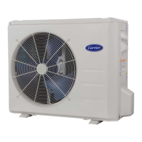
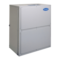
Fig. 1 —Sizes 9K to 36K
NOTES: Read the entire instruction manual before starting the
installation.
Images are for illustration purposes only. Actual
models may differ slightly.
TABLE OF CONTENTS
PAGE
SAFETY CONSIDERATIONS........................................................2
INTRODUCTION ............................................................................3
ACCESSORIES................................................................................3
DIMENSIONS..................................................................................4
CLEARANCES ................................................................................7
INSTALLATION REQUIREMENTS .............................................8
INSTALLATION .............................................................................8
Step 1 - Check Equipment ................................................................8
Step 2 - Mount Unit ..........................................................................8
Step 3 - Condensate Drain Installation .............................................9
Step 4 - Refrigerant Piping ...............................................................10
Step 5 - Evacuate Coil And Tubing System .....................................13
Step 6 - Electrical Connections.........................................................14
WIRING ...........................................................................................14
ELECTRICAL DATA......................................................................15
CONNECTION DIAGRAMS ..........................................................15
START-UP .......................................................................................16
CARE AND MAINTENANCE........................................................16
TROUBLESHOOTING ...................................................................16
OUTDOOR UNIT DIAGNOSTIC GUIDES ...................................17
DUCTLESS START-UP CHECKLIST ...........................................18
Installation Instructions
38MA*R
Outdoor Unit Single Zone Ductless System
Sizes 09 to 36

Questions and Answers:

Carrier 38MA R Series Specifications

General IconGeneral
BrandCarrier
Model38MA R Series
CategoryAir Conditioner
LanguageEnglish

Summary

Safety Considerations

Introduction

Accessories

Dimensions

Clearances

Installation Requirements

Installation Steps

Step 1 - Check Equipment

Inspect the unit for damage and verify it matches job specifications.

Step 2 - Mount Unit

Select location, ensure level position, consider wind and base requirements.

Step 3 - Condensate Drain Installation

Install drain joint and extension hose, ensuring proper sealing and drainage.

Step 4 - Refrigerant Piping

Details on pipe size, length, refrigerant type, and charge amount for different unit sizes.

Step 5 - Evacuate Coil And Tubing System

Explains deep vacuum and triple evacuation methods to remove air and moisture.

Step 6 - Electrical Connections

Guides on power and communication wiring, terminal connections, and grounding.

Wiring

Electrical Data

Connection Diagrams

Start-Up Procedures

Test Operation

Perform test operation after checks, review manuals for additional info.

System Checks

Ensure tubing concealment, drain slope, insulation, and hole sealing.

Explain Customer Information

Inform customer about operation, maintenance, and installation instructions.

Care and Maintenance

Troubleshooting

Outdoor Unit Diagnostic Codes

Lists LED indicators and failure modes for outdoor unit diagnostic codes.

Outdoor Unit Diagnostic Guides

Detailed Unit Diagnostic Codes

Details error codes (E1, F0-F5, P0-P4, P7, J0-J8) and their meanings.

Ductless Start-Up Checklist

Installation Data

Fields for site address, contractor info, job name, and distributor details.

System Details

Collects model and serial numbers for outdoor and indoor units.

Wiring Electrical

Checks wire size, type, connections, and verifies wiring to the correct indoor unit.

Voltage Check

Verifies single-zone wiring connections and voltages at disconnect and terminal blocks.

Piping Verification

Checks leak test, evacuation method, vacuum hold, and line set sizing.

Single Zone Piping Details

Records measured liquid pipe length and calculates additional charge.

Performance Check

Records operational data during testing to ensure proper system performance.

Error Codes Recording

Records any error codes present from indoor, outdoor units, or wall controller.

Related product manuals