8
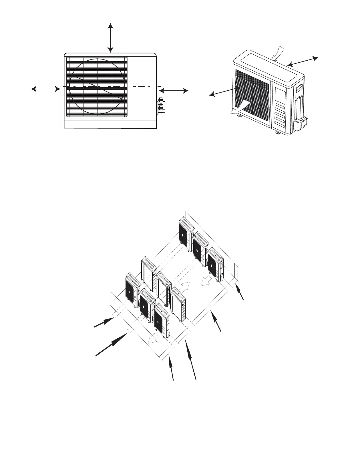
CLEARANCES − OUTDOOR
A
D
B
Air-outlet
Air-inlet
C
E
Fig. 5 - Outdoor Unit Clearance
Table 5—Outdoor Unit Clearance Dimensions
UNIT MINIMUM VALUE in. (mm)
A 24 (610)
B 24 (610)
C 24 (610)
D 4 (101)
E 4 (101)
NOTE: The outdoor unit must be mounted at least 2in. (50mm) above the maximum anticipated snow depth.
118in (300cm) or more
19in (48cm) or more
on a multiple parallel
unit arrangement
4in (10cm) or more on
a single parallel unit
arrangement
24in (60cm)
or more
59in (150cm)
or more on a
multiple parallel
unit arrangement
24in (61cm) or more
on a single parallel
unit arrangement
9.8in (25cm)
or more for
proper airow
24in (61cm) or
more is
recommended
for service
9.8in (25cm)
or more for proper airow
24in (61cm)
or more is
recommended
for service
Fig. 6 - Clearances for multiple units
 Loading...