38MURA: Installation Instructions
Manufacturer reserves the right to change, at any time, specifications and designs without notice and without obligations.
12
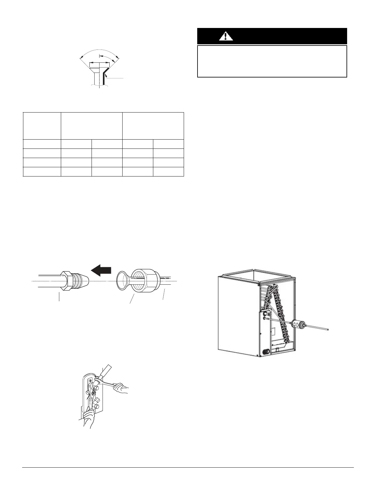
g. Turn the handle of the flaring tool clockwise until the pipe is fully
flared. Flare the pipe in accordance with the dimensions in Table 8.
Fig. 15 — Flare Shape
Table 8 — Tightening Torque
NOTE: Use both a backup wrench and a torque wrench when
connecting or disconnecting pipes to or from the unit.
h. Remove the flaring tool and flare block, then inspect the end of
the pipe for cracks and even flaring.
6. Connect the Pipes
Connect the copper pipes to the indoor unit first, then connect the
pipes to the outdoor unit. Connect the low-pressure pipe first, then
connect the high pressure pipe.
a. Align the center of the two pipes that you will connect.
Fig. 16 — Align the center of the two pipes
b. Tighten the flare nut as much as possible by hand.
c. Using a wrench, grip the nut on the unit tubing.
d. While firmly gripping the nut, use a torque wrench to tighten
the flare nut according to the torque values listed in Table 8.
Fig. 17 — Torque wrench with backup wrench
All tubing bends should be performed with a properly sized tubing bender
to prevent kinking or damaging the tubing.
e. After connecting the copper pipes to the indoor unit, wrap the
power cable, signal cable and the piping together with binding
tape.
NOTE: While bundling these items together, DO NOT intertwine or
cross the signal cable with any other wiring.
f. Thread this lineset through the wall and connect it to the
outdoor unit.
g. Insulate the suction line, including the outdoor unit valves.
NOTE: DO NOT open the service valves until pressure test is
complete.
7. Filter Drier (Heat Pump Drier ONLY)
Refer to Fig. 18 and install the drier as follows:
1.Cut a minimum 4" length of 3/8 tubing and assemble:
a. 3/8” adapter
b. short tubing
c. filter drier
d. lineset
2.Wrap filter drier with damp cloth.
3. Flow nitrogen.
4. Braze assembled components from step 1.
Fig. 18 — Filter Drier Components
The filter drier must be replaced whenever the refrigeration system is
exposed to the atmosphere.
Only use factory specified liquid-line filter driers with rated working
pressures less than 600 psig.
NOTE: Do not install a suction-line filter drier in liquid line.
BRASS
FLARE SIZES
RECOMMENDED
SEATING TORQUE FOR
BRASS FLARE NUTS
FLARE DIMENSIONS (A)
(INCH/MM)
In (mm) Ft-Lbs N-M Min Max
Ø3/8 (9.52) 23.6-28.8 32-39 0.52/13.2 0.53/13.5
Ø3/4 (19) 49.4-74.5 67-101 0.91/23.2 0.93/23.7
Ø7/8 (22) 62.7-81.1 85-110 1.04/26.4 1.06/26.9
Pipe
Indoor unit tubing
Flare nut
Wrap insulation around the piping. Direct contact with the bare
piping may result in burns or frostbite. Ensure the pipe is properly
connected. Over tightening may damage the bell mouth and under
tightening may lead to leakage.
CAUTION
 Loading...

