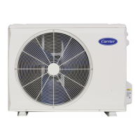
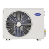
Do you have a question about the Carrier 38MBRC Series and is the answer not in the manual?
Outlines precautions for installation, startup, and servicing of HVAC equipment.
Explains DANGER, WARNING, and CAUTION signal words used with safety alerts.
Provides information for servicing, repairing, and maintaining the 38MBRC heat pumps.
Explains the model numbering system and unit size definitions.
Details recommended wiring methods, sizes, and precautions.
Illustrates connection diagrams for indoor and outdoor units and terminals.
Provides the wiring diagram and component codes for the 36K model.
Provides wiring diagrams and codes for 48K and 58K models.
Illustrates the refrigerant cycle diagram showing component flow.
Provides guidelines for sizing lines, insulation, and refrigerant charge.
Details deep and triple evacuation methods and vacuum pump usage.
Defines sensors and describes main protection functions like compressor restart delay and temperature limits.
Explains FAN mode operation.
Rules for indoor and outdoor fan control in cooling and heating modes.
Explains conditions triggering and terminating defrost mode.
Covers evaporator protection, drying mode, and auto-restart features.
Describes how auto mode selects operating modes based on temperature.
Details display values and meanings for outdoor unit check.
Outlines recommended steps, required tools, and control board measurement notes.
Lists error codes, LED status, and pages for outdoor unit diagnostics.
Explains display values and interpretation for outdoor unit checks.
Describes communication errors and provides troubleshooting flowchart.
Provides a flowchart for diagnosing communication faults.
Instructions for testing DC voltage and reactor resistance.
Describes fan speed issues and provides troubleshooting flowchart.
Describes EEPROM errors and provides troubleshooting steps.
Describes lack phase failure and provides troubleshooting flowchart.
Describes temperature sensor issues and provides troubleshooting flowchart.
Describes IPM malfunction and provides troubleshooting flowchart.
Describes compressor/IPM protection and provides troubleshooting flowchart.
Describes discharge temp protection and provides troubleshooting flowchart.
Describes current/speed issues and provides troubleshooting flowchart.
Describes condenser high temp protection and provides troubleshooting flowchart.
Describes PFC module protection and provides troubleshooting flowchart.
Describes voltage protection and provides troubleshooting flowchart.
Describes high pressure protection and provides troubleshooting flowchart.
Describes PCB-IPM communication error and provides troubleshooting flowchart.
Describes compressor lack phase protection and provides troubleshooting flowchart.
Describes IR chip failure and provides troubleshooting flowchart.
Explains low ambient temperature protection.
Presents pressure data tables and graphs for cooling mode.
Presents pressure data tables and graphs for heating mode.
Step-by-step instructions for disassembling the size 36 unit.
Step-by-step instructions for disassembling the size 48-58 unit.
Instructions for disassembling electrical parts for 36K and 48K-58K models.
Instructions for disassembling the fan assembly and motor.
Instructions for removing the sound blanket.
Instructions for removing the 4-way valve and compressor.
Table of resistance values for sensors T1, T2, T3, T4.
Table of resistance values for sensor T5.
Table for converting between Celsius and Fahrenheit.
| Series | 38MBRC |
|---|---|
| Type | Heat Pump |
| Cooling Capacity | 18, 000 - 60, 000 BTU/h |
| HSPF Rating | Up to 9.5 |
| Refrigerant | R-410A |
| Power Supply | 208/230V |


 Loading...