38MBRC: Service Manual
Manufacturer reserves the right to change, at any time, specifications and designs without notice and without obligations.
5
WIRING DIAGRAMS
Size 36K
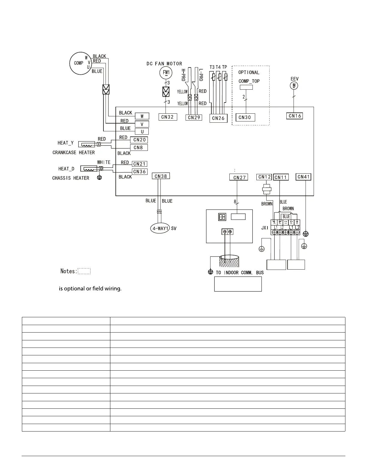
Fig. 3 — Wiring Diagram Size 36K
Table 3 — Wiring Diagram Size 36K Codes
CODE PART NAME
JX1 Terminal Block
COMP_TOP COMP. TOP OLP TEMP. Sensor
EEV Electronic Expansion Valve
FM1 DC Fan Motor
COMP Compressor
HEAT_Y Crankcase Heater
CT1 AC Current Detector
H-PRO High Pressure Switch
L-PRO Low Pressure Switch
SV Reversing Valve
TP COMP. Discharge TEMP. Sensor
T3 COIL TEMP. Sensor
T4 Outdoor Ambient TEMP. Sensor
HEAT_D Chassis Heater
MAIN BOARD
G
6
CN1
CT1
CN4
S2
S1
2
)
(
1
()
Output:230 VAC
Output:230 VAC
Output
Intput: 230 VAC
U~V~W among
phases 0~250VAC
Input:0-5VDC
Connect to FAN
voltage among
phases 0~200VAC
Output:0-12VDC
Output:230 VACOutput:230 VAC
Output: 0-5VDC
Component in the dash line
TO INDOOR UNIT POWER SUPPLY
NOTE: Please use 2-core
shielded wire.
AUXILIARY BOARD
0-5VDC
 Loading...
