38MBRC: Service Manual
Manufacturer reserves the right to change, at any time, specifications and designs without notice and without obligations.
4
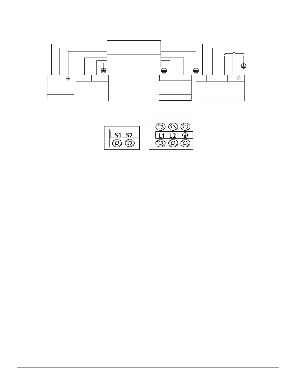
CONNECTION DIAGRAM
Fig. 1 — Connection Diagram Sizes 36K-58K
Fig. 2 — Control and Power Terminals Sizes 36K-58K
NOTES:
1. Do not use thermostat wire for any connection between indoor and outdoor units.
2. All connections between indoor and outdoor units must be as shown. The connections are sensitive to polarity and will generate a fault code.
208-230-1-60
L1
L2
FIELD POWER SUPPLY
Indoor Unit
Power Supply
Low voltage
Nonpolar RS-485
communication
208-230-1-60
Nonpolar RS-485
Low voltage
communication
Outdoor Unit
208-230-1-60
Power Supply
SHIELDED WIRE CONNECTING
OUTDOOR TO INDOOR
To Indoor Unit
Power Supply
S1
S2
L1
(1)L1
(2)L2
L2
P(S1)
GND
Q(S2)
CONNECTING CABLE
OUTDOOR TO INDOOR
 Loading...
