38MBRC: Service Manual
Manufacturer reserves the right to change, at any time, specifications and designs without notice and without obligations.
9
SYSTEM EVACUATION AND CHARGING
Refrigerant tubes and indoor coil should be evacuated using the
recommended deep vacuum method of 500 microns. The alternate triple
evacuation method may be used if the following procedure is followed.
Always break a vacuum with dry nitrogen.
SYSTEM VACUUM AND CHARGE
Using Vacuum Pump
1. Completely tighten the flare nuts (A, B, C, D, E). Fully open all circuits
service valves. Connect the manifold gage charge hose to the charge
port of the low side Master service valve to evacuate all circuits at the
same time (see Fig. 6).
2. Connect charge hose to vacuum pump.
3. Fully open the low side of manifold gage (see Fig. 7).
4. Start vacuum pump
5. Evacuate using the triple evacuation method.
6. After evacuation is complete, fully close the low side of manifold gage
and stop operation of vacuum pump.
7. The factory charge contained in the outdoor unit is good for up to
25ft. (8 m) of line length. For refrigerant lines longer than 25ft. (8
m), add refrigerant as specified in “Additional Charge Table Per
Zone” on page 8.
8. Disconnect charge hose from charge connection of the low side service
valve.
9. Securely tighten caps of service valves.
Fig. 6 — Service Valve
Fig. 7 — Manifold
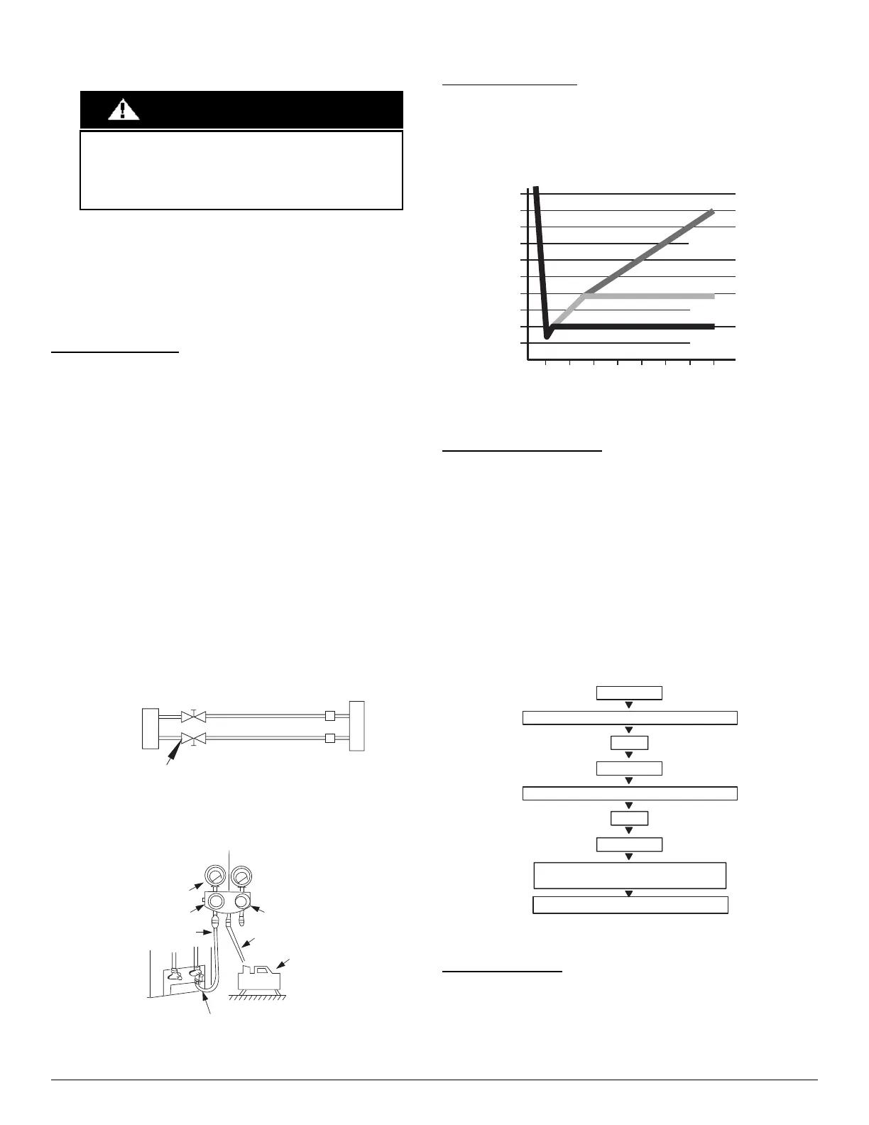
Deep Vacuum Method
The deep vacuum method requires a vacuum pump capable of pulling a
vacuum of 500 microns and a vacuum gage capable of accurately measuring
this vacuum depth. The deep vacuum method is the most positive way of
assuring a system is free of air and liquid water (see Fig. 8).
Fig. 8 — Deep Vacuum Graph
Triple Evacuation Method
The triple evacuation method should be used. Refer to Fig. 9 and proceed
as follows:
1. Pump system down to 500 MICRONS of mercury and allow pump to
continue operating for an additional 15 minutes. Unit must maintain 500
microns or less for 30 minutes or more to ensure a dry system.
2. Close service valves and shut off vacuum pump.
3. Connect a nitrogen cylinder and regulator to system and open until
system pressure is 2 psig.
4. Close service valve and allow system to stand for 10 minutes. During
this time, dry nitrogen will be able to diffuse throughout the system
absorbing moisture.
5. Repeat this procedure as indicated in Fig. 9. System will then be free of
any contaminants and water vapor.
Fig. 9 — Triple Evacuation Method
Final Tubing Check
IMPORTANT: Check to be certain factory tubing on both
indoor and outdoor unit has not shifted during shipment.
Ensure tubes are not rubbing against each other or any sheet
metal. Pay close attention to feeder tubes, making sure wire ties
on feeder tubes are secure and tight.
UNIT DAMAGE HAZARD
Failure to follow this caution may result in equipment damage
or improper operation.
Never use the system compressor as a vacuum pump.
CAUTION
Outdoor Unit
Indoor Unit
Refrigerant
Service Valve
Manifold Gage
500 microns
Low side valve
High side valve
Charge hose
Charge hose
Vacuum pump
Low side valve
01234567
1000
1500
LEAK IN
SYSTEM
VACUUM TIGH
TOO WET
TIGHT
DRY SYSTEM
2000
CHECK FOR TIGHT, DRY SYSTEM
(IF IT HOLDS DEEP VACUUM)
BREAK VACUUM WITH DRY NITROGEN
WAIT
EVACUATE
RELEASE CHARGE INTO SYSTEM
BREAK VACUUM WITH DRY NITROGEN
EVACUATE
WAIT
 Loading...
