Installation Instructions
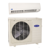
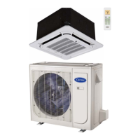
40MVC / 38MVC
40MVQ / 38MVQ
High---W all Duct F ree Split System
Sizes 009 to 024
the environmentally sound refrigerant
NOTE: Read the entire instruction manual before starting the
installation.
TABLE OF CONTENTS
PAGE
PARTS LIST 2.......................................
SAFETY CONSIDERATIONS 3.........................
GENERAL 3.........................................
SYSTEM REQUIREMENTS 3..........................
DIMENSIONS 4......................................
SERVICE VALVE LOCATIONS 4........................
CLEARANCES 5.....................................
INSTALLATION TIPS 6...............................
INDOOR UNIT INSTALLATION 6.......................
OUTDOOR UNIT INSTALLATION 7.....................
INSTALL ALL POWER AND INTERCONNECTING WIRING
TO OUTDOOR UNIT 8--9..............................
INSTALL ALL POWER, INTERCONNECTING WIRING,
AND PIPING TO INDOOR UNIT 10.....................
REMOTE CONTROL INSTALLATION 10.................
SYSTEM VACUUM AND CHARGE 11...................
START--UP 12........................................
TROUBLESHOOTING 13..............................





 Loading...