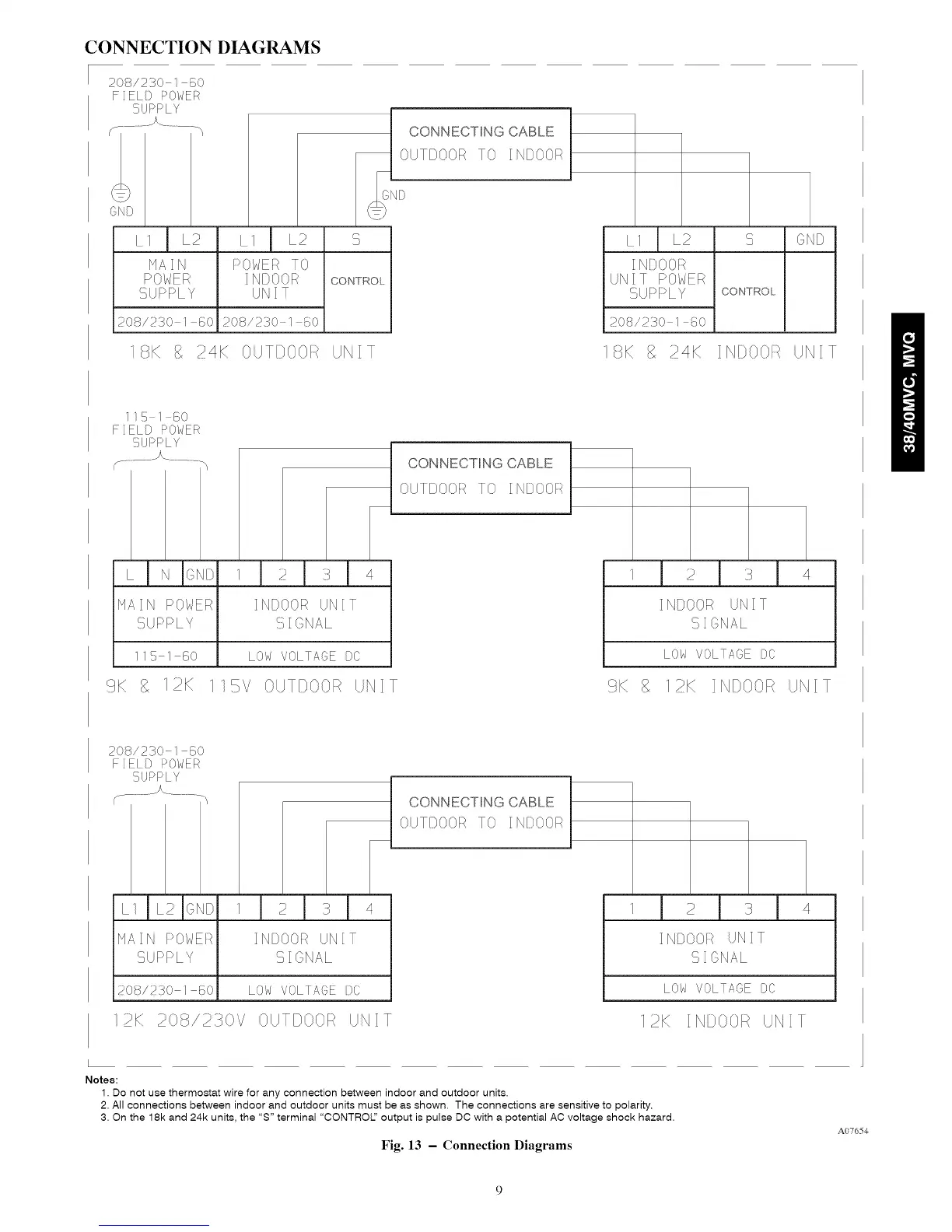
CONNECTION DIAGRAMS
208/230 1 GO
FIELD POWER
SUPPLY
:>O//_EATO [
I NDOOR CONTROL
UNIT
208/2S0 1 60
_S CONNECTING CABLE 1
OUTDOOR TO INDOOR
D
UNIT POWER
SUPPLY CONTROL
208/230 I {i0
8K C}LT[}O0:_ UNIT _IGK 24K IN}OOF/ UNIT
151 GO
FIELD POWER
SU::>I:::>L Y
HAIN POWERI INDOOR UNIT !
!}LPPLY :::}I GNAL
[ 115 1 50 1 LOW VOLTAOE DC
9K 8 12K ]15V OUTDOOR UNIT
CONNECTING CABLE
OUTDOOR TO INDOOR
9K g 12K INDOOR k/NIT
208/230 1 80
FIELD POWER
SUPPLY
INDOO_RUNIT
SIGNAL
LOW VOLTAOE )C
m
!
)K 208/230// OUTDOOR UNIT
CONNECTING CABLE
OUTDOOR TO IN)OOA
I I
12K IN OOR UNIT
Notes:
1. Do not use thermostat wire for any connection between indoor and outdoor units.
2. All connections between indoor and outdoor units must be as shown. The connections are sensitive to polarity.
3. On the 18k and 24k units, the "S" terminal "CONTROL' output is pulse DC with a potential AC voltage shock hazard.
Fig. 13 - Connection Diagrams
A07654
 Loading...
