FILE NO. SVM-07009
– 22 –
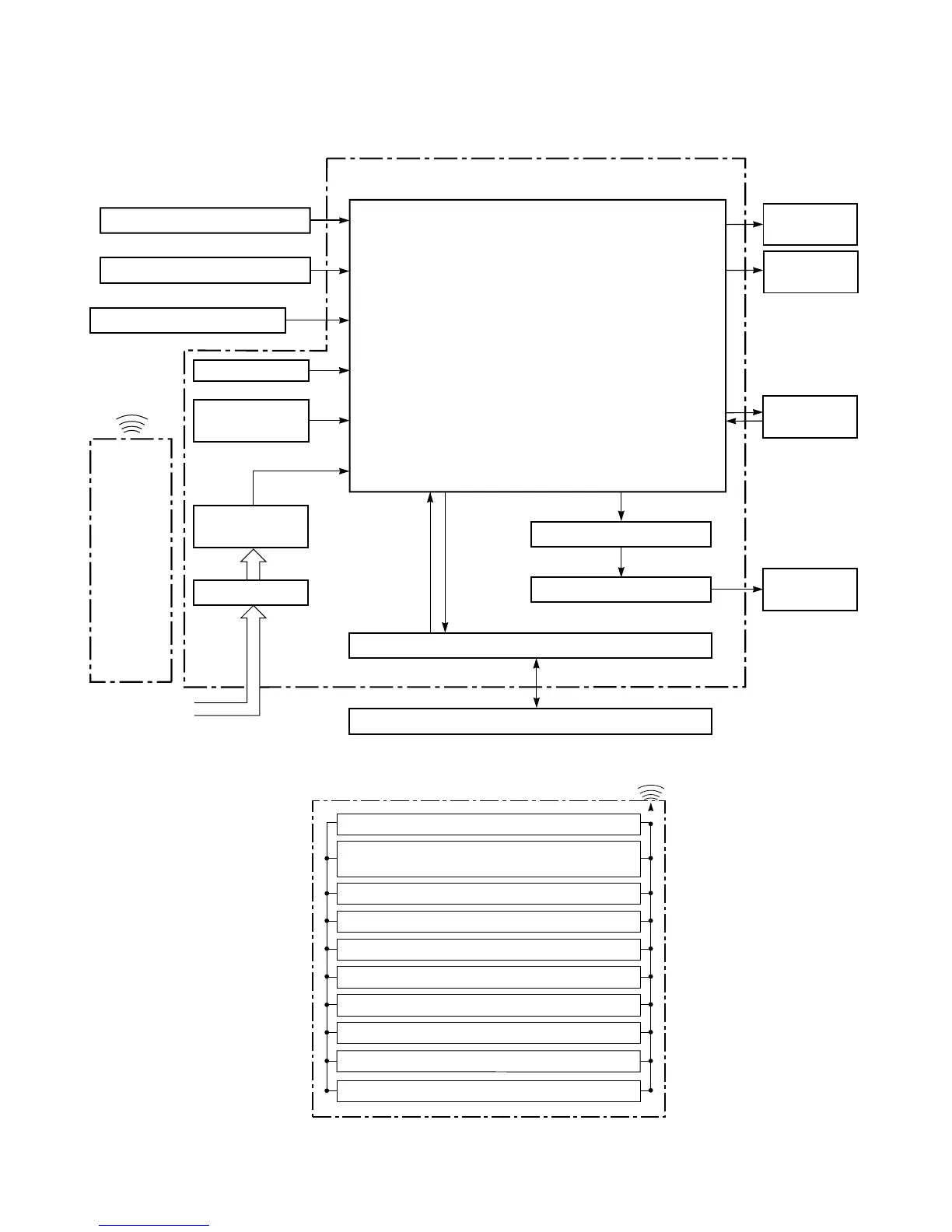
8-1. Indoor Unit
8. CONTROL BLOCK DIAGRAM
Remote Control
Operation (ON/OFF)
Operation Mode Selection
AUTO, COOL, DRY, HEAT, FAN ONLY
Temperature Setting
Fan Speed Selection
ON TIMER Setting
OFF TIMER Setting
Louver Auto Swing
Louver Direction Setting
ECO
Powerful
Infrared
Rays
REMOTE CONTROL
Indoor Unit Control Panel
Heat Exchanger Sensor
Temperature Sensor
Infrared Rays Signal Receiver
Initiallizing Circuit
Clock Frequency
Oscillator Circuit
Power Supply
Circuit
Noise Filter
From Outdoor Unit
M.C.U.
Functions
• Louver Control
• 3-minute Delay at Restart for Compressor
• Motor Revolution Control
• Processing
(Temperature Processing)
• Timer
• Serial Signal Communication
Louver ON/OFF Signal
Louver Driver
Serial Signal Transmitter/Receiver
Serial Signal Communication
Operation
Display
Timer
Display
Louver Motor
Infrared
Rays
Remote
Control
Indoor Fan
Motor
36.7KHz
 Loading...


