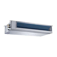
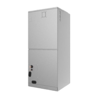
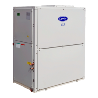
40MBAB: Installation Instructions
Manufacturer reserves the right to change, at any time, specifications and designs without notice and without obligations.
30
TROUBLESHOOTING
For ease of service, the systems are equipped with diagnostic code display LEDs on some outdoor units. The outdoor diagnostic display consists of two
LEDs (red and green) on the outdoor unit board and is limited to a few errors. The indoor diagnostic display is a digital readout on the display panel. If
possible, always check the diagnostic codes displayed on the indoor unit first before consulting a service technician. The diagnostic codes, displayed in
the indoor and outdoor units, are listed in Table 19.
Table 19 — Indoor Unit Diagnostic Guides
NOTE: If the LED display shows DF (Defrost) or FC (Forced Cooling), these are operational codes and, not fault or protection.
For additional diagnostic information, refer to the indoor unit service manual.
DISPLAY ERROR INFORMATION
EH00 Indoor EEPROM Malfunction
EL01 Communication malfunction between the indoor and outdoor units
EH03 Indoor fan speed malfunction
EC51 Outdoor EEPROM malfunction
EC52 Condenser coil temperature sensor (T3) malfunction
EC53 Outdoor ambient temperature sensor (T4) malfunction
EC54 Outdoor unit exhaust temperature sensor error
EH60 Indoor Room Temperature Sensor T1 Error
EH61 Indoor Evaporator Coil Temperature Sensor T2 Error
EH62 Air inlet temperature sensor error
EC07 Outdoor DC fan speed malfunction
EH0b Indoor PCB and display board communication error
ELOC Refrigerant leakage detection
EHOE Indoor water level warning error
FL09 New and old platform match malfunction
PC00 Inverter module (IPM) protection
PC01 Over high voltage or over low voltage protection
PC02 High temperature protection of compressor top/IPM temperature protection
PC04 Inverter compressor drive error
PC03 Low pressure protection
PC0L Low temperature protection of outdoor unit
---- Indoor units mode conflict

 Loading...


