40MBFAQ: Service Manual
Manufacturer reserves the right to change, at any time, specifications and designs without notice and without obligations.
19
DIAGNOSIS AND SOLUTION (CONT.)
Index
1. Indoor or Outdoor DC Fan Motor (control chip is in fan motor)
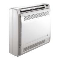
Power on the unit and when the unit is in the STANDBY mode, measure the voltage of pin1-pin3, pin4-pin3 in the fan motor connector. If the voltage
value is not in the range shown in Table 7, the PCB has malfunctioned and needs to be replaced.
Table 7 — Signals
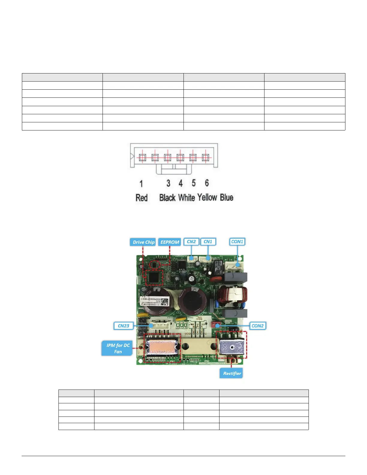
2. Indoor DC Fan IPM Board (Duct and Ceiling-floor Unit)
NO. COLOR SIGNAL VOLTAGE
1 Red Vs/Vm 192V~380V
2 --- --- ---
3BlackGND0V
4 White Vcc 13.5~16.5V
5 Yellow Vsp 0~6.5V
6 Blue FG 13.5~16.5V
PORT DESCRIPTION PARAMETER REMARK
CON1 Power input for the PCB 230V/AC
CN1 Communication with main PCB DC
CN2 Test Port 5V/DC For debugging board
CN23 UVW output for DC fan motor
CON2 Ports for reactor
 Loading...