40MBFAQ: Service Manual
Manufacturer reserves the right to change, at any time, specifications and designs without notice and without obligations.
25
DIAGNOSIS AND SOLUTION (CONT.)
PC 01 (Over voltage or too low voltage protection Diagnosis and Solution)
Description: Abnormal increases or decreases in voltage are detected by checking the specified voltage detection circuit.
Recommended parts to prepare:
• Power supply wires
• IPM module board
•PCB
•Reactor
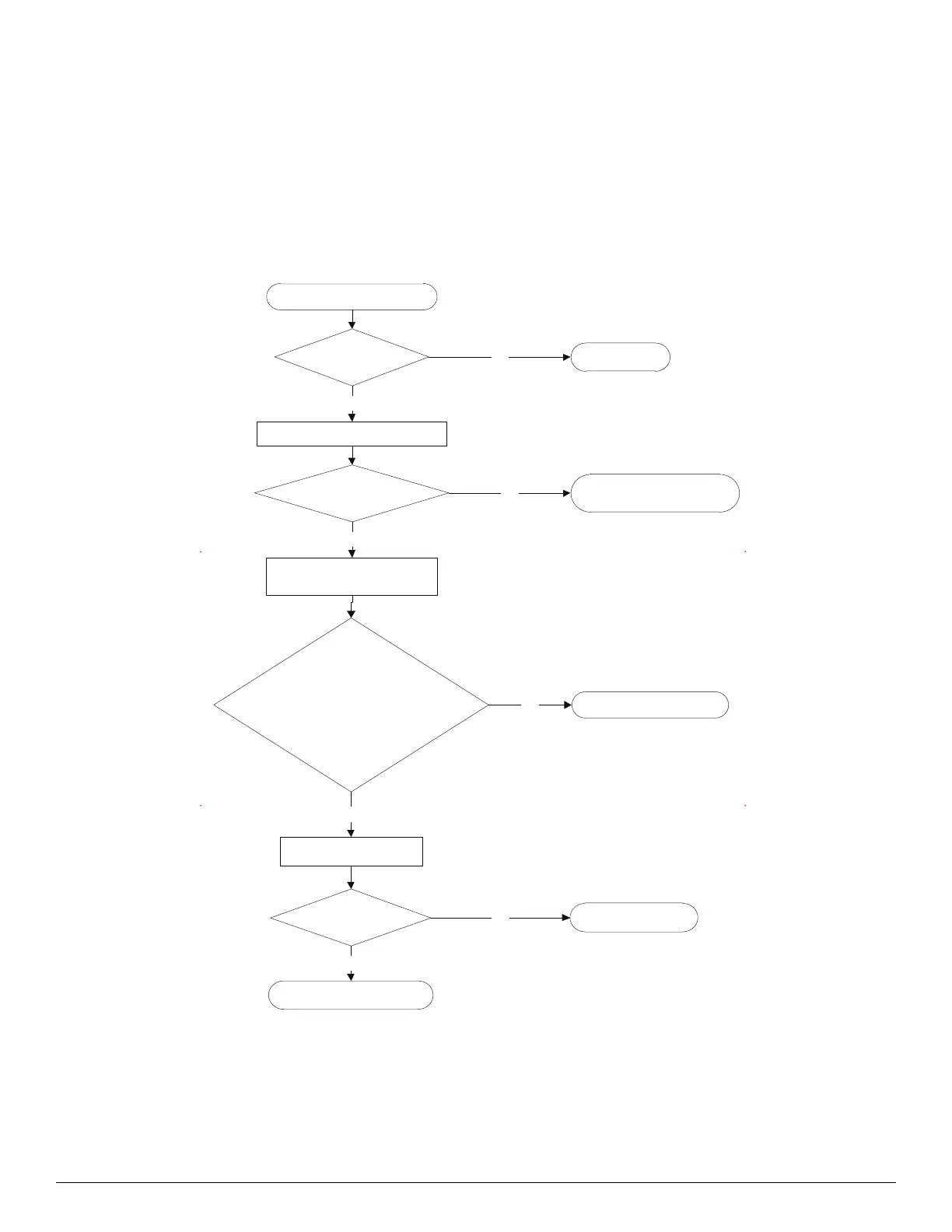
Troubleshooting
NOTE: For certain models, the outdoor PCB cannot be removed separately. In this case, the outdoor electric control box should be replaced
as a whole.
Check the power supply .
Is it in working order ? Turn o the unit.NO
Check the connections and wires.
YES
Are they in working order ?
Ensure proper connections or
replace the wires .
NO
Power on and measure the
voltage between P and N .
YES
Replace the IPM board.NO
Check the reactor.
YES
Is it in working order? Replace outdoor PCB.NO
Replace the reactor.
YES
While the unit is in the STANDBY mode,
is the voltage between P and N around
DC 310V, 340V, or 380V? When starting up
the unit, it is in the 220V~400V?
 Loading...