OG-40MBFQ-04 Specifications subject to change without notice. 3
PART NAMES
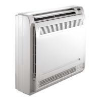
Fig. 1 — Part Names
1. Air flow louver (at air outlet)
2. Air inlet (with air filter inside)
3. Installation section
4. Wireless remote controller
5. Display Panel
6. Drain pipe (field supplied)
INDOOR UNIT DISPLAY PANELS
Fig. 2 — IR (Infrared) Receiver Display Panel
NOTE: Images within this manual are for illustration purposes only. Actual model may differ slightly.
refrigerant pipe
(D. gas side)
D. Connecting point of
refrigerant pipe
(E. Liquid side)
Drain point
Sizes 09K -12K
Sizes 18K - 58K
1
5
2
Turbo
Infrared signal receiver
Operation lamp
Alarm indicator
Temporary button
Temperature indicator
Timer indicator
PRE-DEF indicator (cooling and heati)ng type
or FAN ONLY indicator (cooling only type)
MANUAL
Sizes 18-58