76
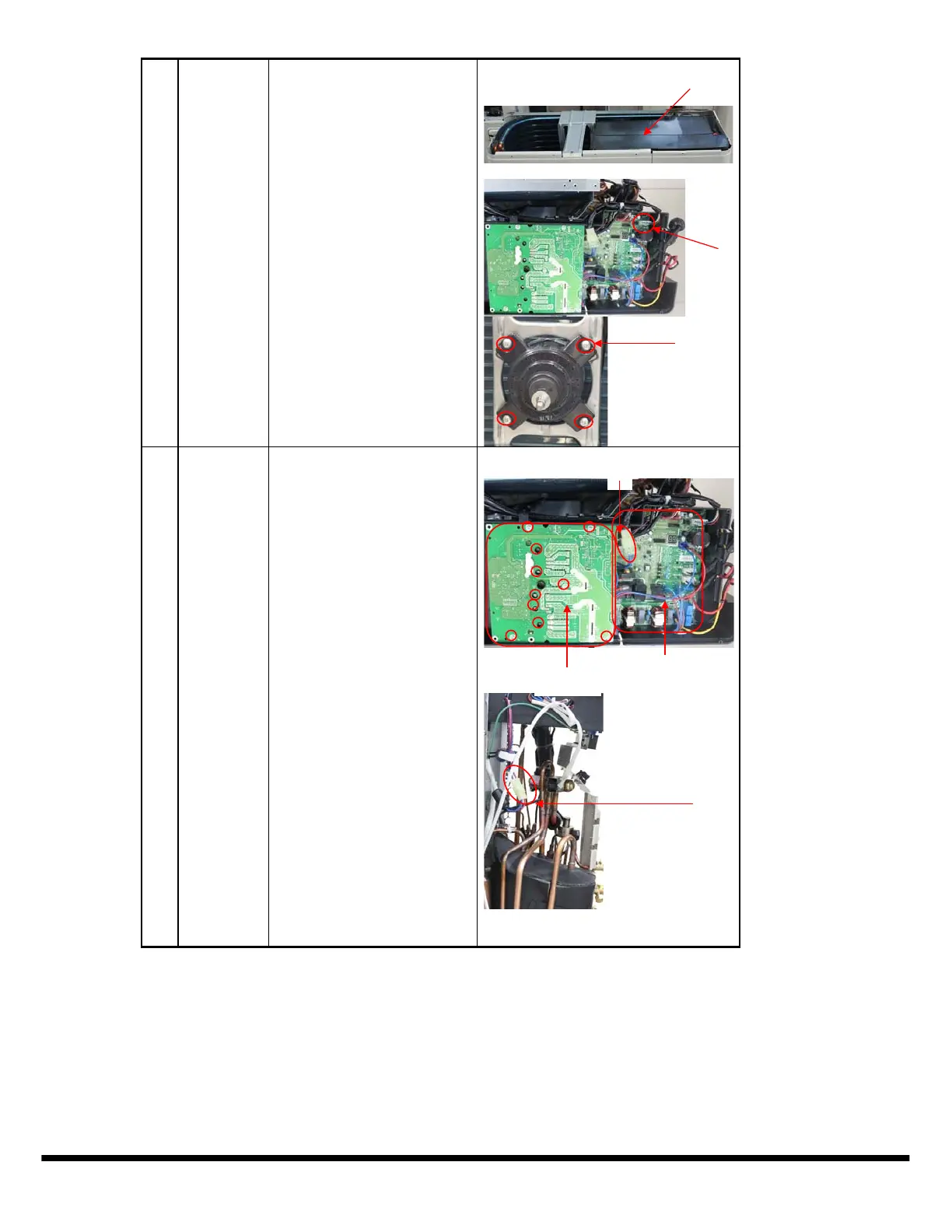
4) Remove the electrical
control box cover.
5) Disconnect the fan motor
connector CN37(5p,white) from
the PCB board.
6) Remove the fan motor
after unfastening four fixing
screws.
3 Electrical
parts
How to remove the electrical
parts.
1) Perform work of item 1,2.
2) Remove the ten screws
fixing the IPM board.
3) Unfasten the connector
of the reactor.
4) Unfasten the connector
of the compressor.
5) Disconnect following 5
pieces of connection wires and
connectors between IPM and
PCB.
IPM board
PCB board
䐡
ĺ
Copyright 2015 CAC/B D P. S 7310 W. Morris St. S Indianapolis, IN 46231
Manufacturer reserves the r ight to change, at any time, specifications and designs without notice and without obligations.
Catalog No.38MGQ---01SM
Replaces: NEW
Edition Date: 08/ 15
 Loading...