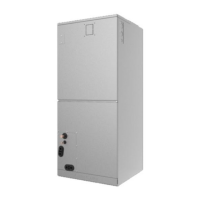
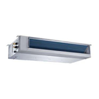
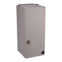
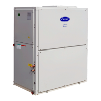
40MUAA: Installation Instructions
Manufacturer reserves the right to change, at any time, specifications and designs without notice and without obligations.
20
ELECTRICAL DATA
Table 11 — Electrical Data
CONNECTION DIAGRAMS
Scenario 1 - Non-Polarity RS485 Communication + 24V Thermostat
This is the preferred method when using a 24V thermostat and when the indoor unit communicates with the outdoor unit via RS485 protocol.
Fig. 49 —Scenario 1
Scenario 2 - Non-Polarity RS485 Communication
This is the preferred method of control with wired controller KSACN1001(Not included)
Fig. 50 —Scenario 2
UNIT SIZE V-PH-HZ
INDOOR FAN
FLA HP W-Out
System Power
Factor (%)
MAX FUSE CB AMP
When powered independently
18K
208-230/1/60
2.0 1/3 250 69
15
24K 3.0 1/3 250 89
30K 3.5 1/2 375 96
36K 3.5 1/2 375 98
48K 5.0 3/4 560 98
60K 7.0 1 750 98
Outdoor Unit
RCGY1Y2BW W1W2EDHL
24V Thermostat
Indoor Unit Display Board
RCGY1Y2BWW1W2EDHL S1S2
S1 S 2R C Y1 Y2 B W D L
Control
Board
ON
SW1
1 2 3 4
Default Setting
Refer to the wiring nameplate for the wiring method.
DO NOT connect 24V AC to S1-S2, as this will damage the
system.
WA R N I N G
RCY1Y2BW D L
Outdoor Unit
Indoor Unit Display Board
RC L GY1
Y1/Y2
BWW1W2EDH
S1 S2
S1 S 2
Wired
Controller
Wired
Controller
HA HB
HA HB
Control
Board
ON
SW1
1 2 3 4

 Loading...


