Manufacturer reserves the right to discontinue, or change at any time, specifications or designs without notice and without incurring obligations.
Catalog No.20-40VMW005-030-01 Printed in U.S.A. Form 40VMW-6SI Pg 18 2-20 Replaces: 40VMW-5SI
© Carrier Corporation 2020
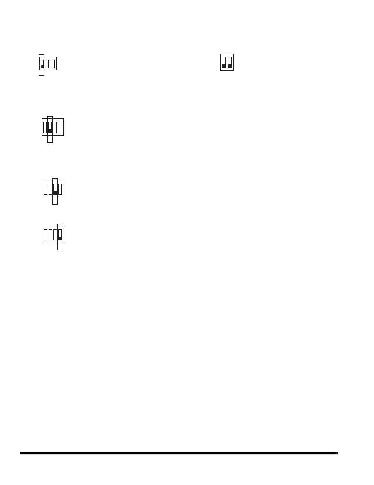
APPENDIX A — DIP DWITCH SETTINGS
There are two DIP switches on the main board. Figures A and B show the settings for each parameter controlled by a switch. Switches are
shown in the default settings.
POSITION 1 — START-UP
POSITION 2
POSITION 3 — NOT USED
POSITION 4 — INDOOR UNIT IDENTIFICATION
Fig. A — SW1 SETTINGS
POSITION 1, 2 — NOT USED
Fig. B —SW8 SETTINGS
OFF — Auto Addressing Mode (Default)
ON — Factory Test Mode
OFF — Normal Mode (Default)
ON — Factory Self-Checking Mode
OFF — Standard Indoor Unit (Default)
ON — Mode Priority Indoor Unit (HP Only)
(IDU address must be 63)