Do you have a question about the Carrier i-Vu CCN Router and is the answer not in the manual?
Explains the router's role as a Gateway or Bridge connecting Ethernet LAN to CCN.
Details about device drivers, maximum controllers, power requirements, and communication ports.
Information on the microprocessor, memory capacity, and the battery-backed real-time clock.
Covers battery function, surge protection, status indicators, and operating/storage environmental conditions.
Emphasizes disconnecting power before wiring to prevent shock or damage.
Provides physical dimensions, mounting hole details, and recommended panel depth.
Lists the device weight and its certifications including UL, CE, and FCC.
Instructions on how to mount the router in an enclosed panel, with handling precautions.
Step-by-step guide for connecting the power supply, including voltage verification.
Details wiring connections for CCN devices on Port S1, including jumper settings and shield handling.
Outlines using Network Service Tool for commissioning and setting Host IP, Subnet Mask, and Default Gateway.
Explains selecting Device Type as Gateway or Bridge and configuring the CCN/Ethernet Gateway Address.
Instructions for erasing data and restoring factory defaults, including a caution.
Describes the meaning of LED status indicators and common error codes with possible solutions.
Provides steps for safely replacing the device's internal 10-year lithium battery.
Information regarding FCC Part 15 compliance for Class A digital devices and potential interference.
Notes on CE Class A product compliance and BACnet International standards responsibility.
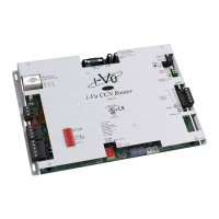
The i-Vu® CCN Router is a crucial component of the i-Vu® system, designed to bridge an Ethernet-based Local Area Network (LAN) with the Carrier Comfort Network (CCN). This device offers versatility, functioning either as a Gateway or a Bridge, depending on the specific configuration of the building or facility's network. Its primary role is to facilitate communication between the i-Vu® web server, which typically resides on the Ethernet, and the various CCN devices within the system. By allowing the use of existing LAN wiring, the i-Vu® CCN Router provides an efficient and cost-effective solution for integrating CCN elements into a building's infrastructure.
When configured as a Gateway, the i-Vu® CCN Router acts as the primary access node from the Ethernet to the CCN bus. In this mode, it is responsible for maintaining a comprehensive routing table of all CCN system elements, ensuring seamless data flow and control. It connects directly to the CCN's primary bus (Bus 0) and, like other CCN system elements, occupies a unique address on the CCN. This configuration is ideal for systems where a central i-Vu® web server needs to manage and monitor all connected CCN devices.
Alternatively, the i-Vu® CCN Router can be configured as a Bridge. In this application, it serves as a CCN/Ethernet interface device, connecting separate CCN buses. This setup typically requires an additional i-Vu® CCN Router to function as a Gateway. As a Bridge, each i-Vu® CCN Router occupies a unique bus and element address on the CCN, with its system element number on the primary bus identifying the secondary bus number. This allows for the expansion of CCN networks and the integration of additional CCN elements into the system, providing greater flexibility in network design.
The i-Vu® CCN Router is equipped with one EIA-485 port for connecting to the CCN bus and/or a CCN Service Tool, and one 10/100Base-T Ethernet port for connecting to the building LAN. Each router can support up to 140 CCN devices, making it suitable for a wide range of applications. Beyond its communication functions, the router also plays a vital role in data management by storing trend data and time schedules for the connected CCN devices. This capability ensures that critical operational data and scheduling information are readily available, even in the event of network interruptions.
For initial setup and configuration, the i-Vu® CCN Router must be commissioned using the Network Service Tool on Port S1. This involves connecting the tool directly to Port S1, uploading the router's default CCN address, and then changing it to avoid conflicts with other Carrier equipment. A static IP address is required for the router, which is configured through the Service Configuration Table IP_CONF. This table allows for the entry of the device manager's IP address, subnet mask, and default gateway, all provided by the LAN administrator. The device type (Gateway or Bridge) is also selected during this configuration process, determining the router's operational mode within the CCN system.
Maintenance features for the i-Vu® CCN Router include status indicators and a battery backup system. The device features LED status indicators for EIA-485 CCN communication, Ethernet port communication, and low battery status. A seven-segment status display provides information on running, error, and power status. These indicators are crucial for quick troubleshooting and monitoring the router's health. The Module Status LED can display various error codes, each pointing to specific issues such as the controller not being downloaded, custom equipment errors, memory full, setup errors, or system errors. Detailed instructions are provided for addressing each of these error conditions, including obtaining Module Status Reports and contacting technical support if necessary.
The i-Vu® CCN Router is designed with a battery-backed real-time clock that keeps track of time even during power failures. A 10-year Lithium CR123A battery ensures that critical data, including time, graphics, control programs, editable properties, schedules, and trends, is retained for up to 720 hours during power outages. To conserve battery life, the driver can be set to turn off battery backup after a specified number of days, relying on the archive function for data restoration upon power return. A low battery is indicated by a dedicated LED and an alarm in the i-Vu® application, touchscreen devices, and Field Assistant. Replacing the battery is a straightforward process, involving turning off power, prying up the battery clip, removing the old battery, inserting a new one with correct polarity, and then downloading the i-Vu® CCN Router to ensure all data is restored.
The device also incorporates built-in surge and transient protection for power and communications, complying with EN61000-6-1 standards. Incoming power and network connections are safeguarded by non-replaceable internal solid-state polyswitches that automatically reset once the fault condition is resolved. Additionally, these connections are protected against transient excess voltage/surge events lasting no more than 10 milliseconds. For enhanced protection on serial EIA-485 networks, it is recommended to place a PROT485 at each point where wires enter or exit the building.
Mounting the i-Vu® CCN Router involves screwing it into an enclosed panel using the provided mounting slots, ensuring adequate space for wiring. Proper handling precautions are emphasized, such as avoiding contamination of the circuit board, not touching components or leads, handling by the edges, isolating from high voltage or electrostatic discharge, and ensuring proper grounding. Wiring for power involves turning off the power switch, removing power from the supply, connecting transformer wires to the screw terminal connector, and verifying the voltage before inserting the connector back into the router. Once powered on, the Run LED should blink, and the Module Status LED will display a chase pattern when the router is operating without errors.
To wire CCN devices on Port S1, the router's power must be off, and the communications wiring checked for shorts and grounds. The Port S1 485/232 jumper must be set to EIA-485, and the 2/4 jumper to 485-2w. The router's Port S1 is then connected to the CCN bus, maintaining consistent polarity throughout the network segment. The CCN Shield should be tied back or daisy-chained if the router is not at the end of the bus.
In cases of severe issues, the i-Vu® CCN Router can be formatted to erase all archived information and user-configuration settings, restoring factory defaults. This process involves turning off the power, holding down the Format button while turning power on, and continuing to hold until the module status LED displays 8 and then 0. After formatting, the Bus and Element number revert to 0, 1, which must be reset using the Network Service Tool, and all content, including control programs, drivers, and parameters, must be downloaded from the i-Vu® interface. This feature is recommended only under the guidance of Carrier Control Systems Support due to the loss of custom settings.
| Ethernet Ports | 1 |
|---|---|
| CCN Ports | 1 |
| Protocols Supported | BACnet, CCN |
| Power Supply | 24VAC |
| Operating Temperature | 32°F to 122°F (0°C to 50°C) |