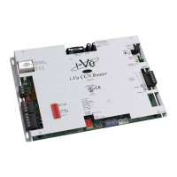
Mounting and wiring
i-Vu® CCN Router CARRIER CORPORATION ©2021
Installation Guide All rights reserved
4
To mount the i-Vu® CCN Router
WARNING
When you handle the i-Vu® CCN Router:
• Do not contaminate the printed circuit board with fingerprints, moisture, or any foreign material.
• Do not touch components or leads.
• Handle the board by its edges.
• Isolate from high voltage or electrostatic discharge.
• Ensure that you are properly grounded.
Screw the i-Vu® CCN Router into an enclosed panel using the mounting slots on the cover plate. Leave about 2 in.
(5 cm) on each side of the controller for wiring.
To wire for power
1 Make sure the i-Vu® CCN Router’s power switch is in the OFF position to prevent it from powering up before
you can verify the correct voltage.
2 Remove power from the power supply.
3 Pull the screw terminal connector from the router's power terminals labeled 24 Vac/Vdc and Ground.
4 Connect the transformer wires to the screw terminal connector.
5 Apply power to the power supply.
6 Measure the voltage at the i-Vu® CCN Router’s power input terminals to verify that the voltage is within the
operating range of 21.6 – 26.4 Vac or 23.4 - 28.6 Vdc.
7 Insert the screw terminal connector into the i-Vu® CCN Router's power terminals.
8 Turn on the i-Vu® CCN Router's power.
9 Verify that the Run LED (a dot in the lower right corner of the Module Status LED) begins blinking. The Module
Status LED will display 8 for about 5 seconds and then reverts to 0, until controllers have been found and
downloaded. There is a chase pattern when the router is running with no errors.
 Loading...