8
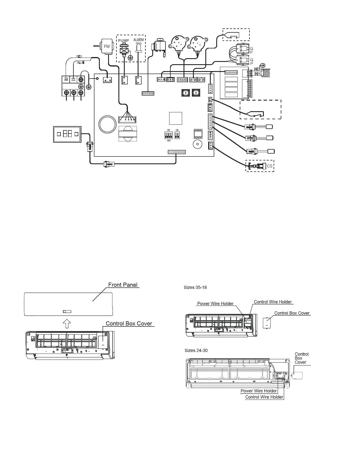
POWER AND CONTROL WIRING —
1. Lift up the front panel and look for the control box cover
as shown in Fig. 11.
Fig. 11 —Accessing Control Box Cover
2. Remove the control box cover plate and look for the
power and control wire holders to route the wires to the
proper terminals as shown in Fig. 12.
Fig. 12 —Removing Control Box Cover
LEGEND
ACB — Auxiliary Control Board
ALARM — Warning Lamp (Optional)
CS — Condensate Switch (Optional)
EEV — Electronic Expansion Valve
FM — Indoor Fan Motor
GM — Swing Motor
MDC — Multiport Distribution Controller
PUMP — Pump Motor (Optional)
T1 — Room Temp. Sensor
T2A — Inlet Pipe Temp. Sensor
T2B — Outlet Pipe Temp. Sensor
XP1-4/XS1-6 — Connectors
XT1 — Terminal
RED
BLUE
TMC
EEV
To Wired Controller Bus
ON/OFF
SWITCH
T2B
T1
main control Board
CN1
CN6
CN5
CN2
CN16
Y/G
GM
XS4
XP4
XS3
XP3
WHITE
XS2
CN18
CN24
CN8
ENC2
CN7
CN14CN54
CN3
GM
CN53
CN4 CN10 CN30
CN19
XS1
XP1
RED
HA
HB
ABC interface
To outdoor / indoor
MDC comm. bus
CN1
CN3
CN2
AUXH
HTON
CTON
FAN
L1 L2
XS5
XS6
BLUE
P
Q
P
Q
POWER IN
Occupancy sensor/
ON-OFF (Dry contact)
Fig. 10 — 40VMW005-030 Typical Wiring Diagram