Guide specifications
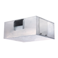
Fan Coil Unit
Horizontal Cabinet Model, Ducted
HVAC Guide Specifications
Size Range: 800 to 4000 Nominal Cfm
Carrier Model Number: 42BH
Part 1 — General
1.01 SYSTEM DESCRIPTION
Horizontal, 2-pipe or 4-pipe, belt-driven, galvanized
casing model fan coil unit forducted installation above
the ceiling, with full access to internal components.
1.02 QUALITY ASSURANCE
Each coil shall be factory tested for leakage at 350
psig air pressure with coil submerged in water. Insu-
lation and adhesive shall meet NFPA-90A require-
mentsforflamespread and smoke generation. Factory-
installed motors shall be UL approved.
1.03 DELIVERY, STORAGE AND HANDLING
Unit shall be handled and stored in accordance with
the manufacturer’s instructions.
Part2—Products
2.01 EQUIPMENT
A. General:
Factory-assembled, horizontal, draw-thru type fan coil
unit for ducted installation above theceiling. Unit shall
be complete with water coils, fan(s), motor, belt drive,
drain pan, and filter.
B. Casing:
Constructionshallbe heavy-gage galvanized steel,lined
with one-in. thick glass fiber thermal/acoustical insu-
lation. Supply and return duct connection shall be one
in. thick and 2 in. long, respectively. Removable side
panels shall be provided for access to the fan/motor
assembly. Drain pan shall be constructed of galva-
nized steel, extending under the full length and width
of the coil(s) and pitched for positive drainage. The
inside surface of the drain pan shall be coated with
closed cell fire-retardant, foam insulation.
C. Fans:
Belt-driven,double-widthfanwheelsshallhaveforward-
curved blades and be statically and dynamically bal-
anced. Fan drive shall consist of variable-pitch motor
pulley, fixed-pitch fan pulley and V-belt. Fans and
scrolls shall be of galvanized steel.
D. Coils:
Standard unit shall be equipped with a 4-row coil for
installation in a 2-pipe system and additional rows of
coil shall be provided for installation in a 4-pipe sys-
tem as described in the Special Features section. Coils
shall have
1
⁄
2
-in. copper tubes, aluminum fins bonded
tothetubes by mechanicalexpansionand have awork-
ingpressure of 250 psig. Eachcoil shallhave a manual
air vent and sweat connections for copper tubes.
E. Operating Characteristics:
A single-circuit coil unit installed in a 2-pipe system
shall be capable of providing heating or cooling as
determined by the operating mode of the central wa-
ter supply system. A double-circuit coil unit installed
in a 4-pipe system shall be capable of providing se-
quenced heating and cooling.
F. Motor(s):
Fan motors shall be open, drip proof, single-speed,
60 Hz, 1750 rpm or 50 Hz, 1425 rpm, either single
or 3-phase, suitable for continuous duty at 104 F
(40 C). Single-phase motors are capacitor start resil-
ient base mounted, include automatic reset thermal
overload protection and are available in 115, 208,
or 230 volts (60 Hz) or 110 or 220 volts (50 Hz).
Three-phase motors are rigid base mounted and are
available in 208, 230, or 460 volts (60 Hz) or 190
or 380 volts (50 Hz).
G. Special Features:
Certain standard features are not applicable when the
features designated by * are specified. See your local
Carrier Sales Office for amending specifications.
* 1. Coils
a. Unit coil(s) shall be equipped with automatic
air vent(s).
b. Unit shall be equipped with a high-capacity
6-row coil for installation in a 2-pipe system.
c. For installation in a 4-pipe system, unit shall
be equipped with either a 4-row cooling/1-
row hot water heating split-circuit coil, or a
4/2, 6/1, or 6/2 split-circuit coil as required.
d. Unit shall be equipped with a 4-row cooling/
1-row steam heating or 6-row cooling/1-row
steam heating split-circuit coil for installation
in a 4-pipe system.
e. Unit shall be equipped with a high-capacity,
6-row cooling/1-row steam heating split-
circuit coil for installation in a 4-pipe system.
f. Unit shall be equipped with either a 4-row
DX cooling coil or a 6-row DX cooling coil
as required.
g. For installation in a 4-pipe system the unit
shall be equipped with either a 4-row DX
cooling/1-row heating split-circuit coil or a
4/2, 6/1, or 6/2 split-circuit coil as required.
* 2. Filters
a.
A one-in. permanent filter shall be installed
in the unit.
b. Extra one-in. permanent or throwaway fil-
ters shall be furnished for field installation as
indicated on the equipment schedule.
26
 Loading...