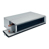
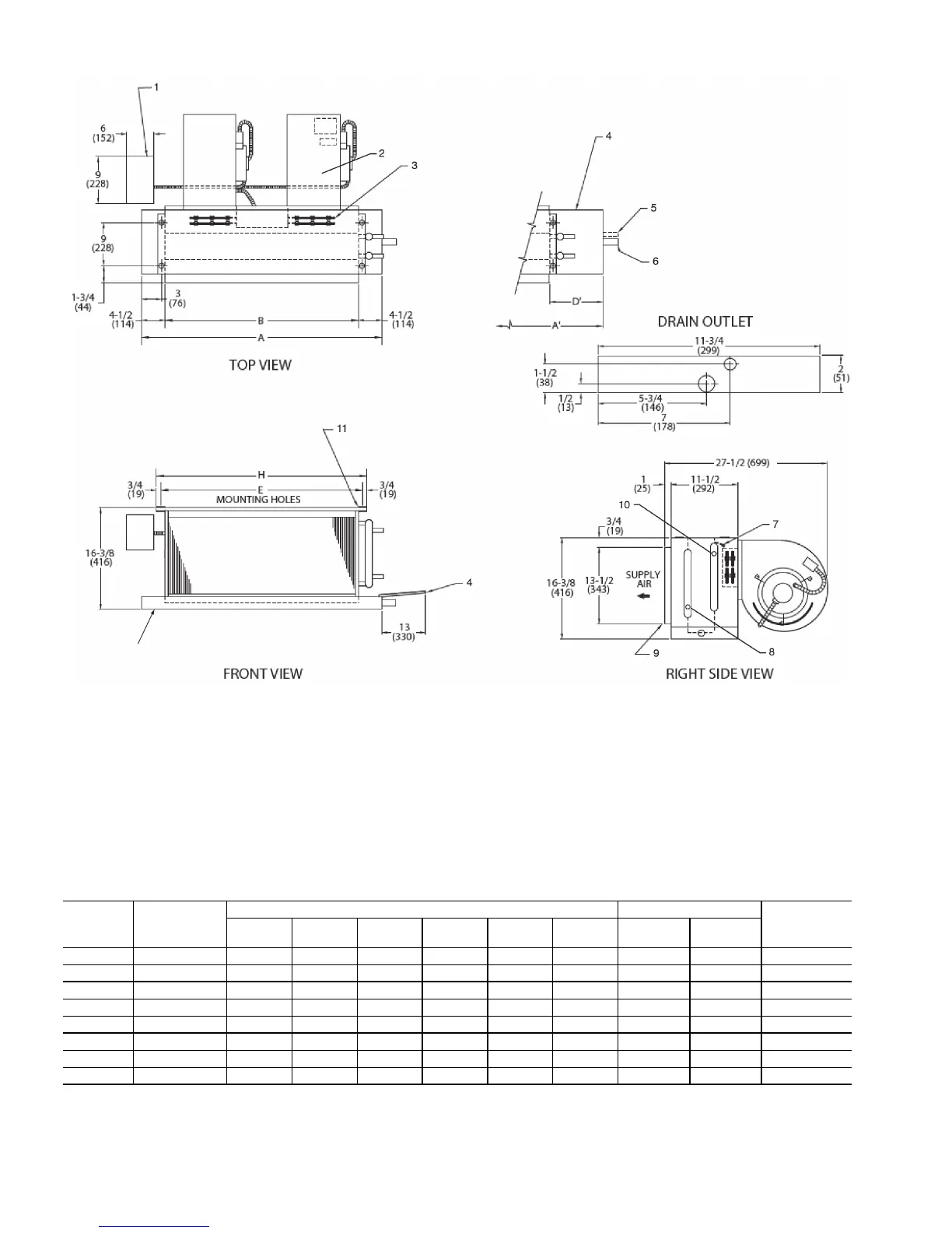
Fig. 24 — 42DA Furred-In Ceiling Unit with Electric Heat Dimensions
*Unit weights are based on dry coils and minimum rows. Weights exclude packaging, valves, and other components.
UNIT SIZE
NOM
AIRFLOW
(cfm)
DIMENSIONS (in. ±
1
/
8
) QTY/UNIT
UNIT
WEIGHT*
(lb)
AA’BD’E HBlowerMotor
06 600 23 32 14 13
1
/
2
17 18
1
/
2
11 64
08 800 28 37 19 13
1
/
2
22 23
1
/
2
11 79
10 1000 32 42 23 14
1
/
2
26 27
1
/
2
11 90
12 1200 37 47 28 14
1
/
2
31 32
1
/
2
2 2 108
14 1400 42 52 33 14
1
/
2
36 37
1
/
2
2 2 119
16 1600 47 56 38 13
1
/
2
41 42
1
/
2
2 2 124
18 1800 52 62 43 14
1
/
2
46 47
1
/
2
2 2 141
20 2000 56 66 47 14
1
/
2
50 51
1
/
2
2 2 151
a42-4120
LEGEND
1— Motor Junction Box
2— Motor-Blower Assembly
3— Electric Strip Heater Element (optional)
4— Auxiliary Drip Lip (optional, shipped loose)
5— Tell-Tale Drain (optional)
6— Drain Connection,
7
/
8
-in. OD
7— Air Vent,
1
/
8
-in. MPT
8— Supply Connection
9— Supply Duct Collar, 1 in.
10 — Return Connection
11 — Mounting Holes (four,
3
/
4
-in. diameter) have Rubber
Grommets with
3
/
8
-in. holes.
NOTES:
1. Right hand unit shown; left hand unit opposite. Coil connection
locations are ±
5
/
8
inch.
2. Sizes 06, 08 and 10 have one motor, one blower; sizes 12
through 20 have 2 motors, 2 blowers.
3. Standard 4-row coil shown. Other coil option dimensional data
available on request.
4. For optional coil connections, view 42DA-203-1 using the Fan
Coil Builder.
5. Fan switch, wall plate not shown.
6. Galvanized finish provided as standard.
7. Dimensions are in inches (mm).