Fig. 32 — Piping Connection Positions
FIELD PIPING CONNECTIONS*
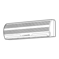
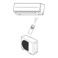
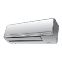
WALL UNITS, FURRED-IN
Pipe to stub connections at the side of unit.
or into optional piping compartment. Optional piping compart-
ment is required if valves are factory installed. Factory-installed
valve package is limited to one 2-way or 3-way motorized valve
and 2 hand valves.
*Location of field piping connections will vary depending on number of coil rows on factory-supplied coil or
arrangement of factory-supplied valves.
a42-4177
HYDRONIC COIL ARRANGEMENT
VERTICAL FLOOR UNITS — 42VB, VE, VF
Pipe into cabinet end compartment (opening in
bottom and back).
VERTICAL FLOOR UNITS — 42VA, VC
Pipe to external connections (no cabinet).
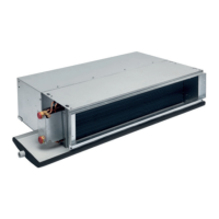
CEILING UNITS (EXPOSED) — 42CG, CK, DE, DF
Pipe through knock-outs in rear of cabinet to coil and
valve package connections.
CEILING UNITS (CONCEALED) — 42CA, CE, CF, DA, DC
Pipe to connections extending from end of unit.
VERTICAL UNITS — 42DD
Pipe to stub connections extending from side of unit.