44
Table 5 — Piping Components (cont)
LEGEND *Check all system component pressure ratings (coils, values,
pumps, etc.) with manufacturer and any applicable local or national
piping codes prior to specifying system pressure rating.
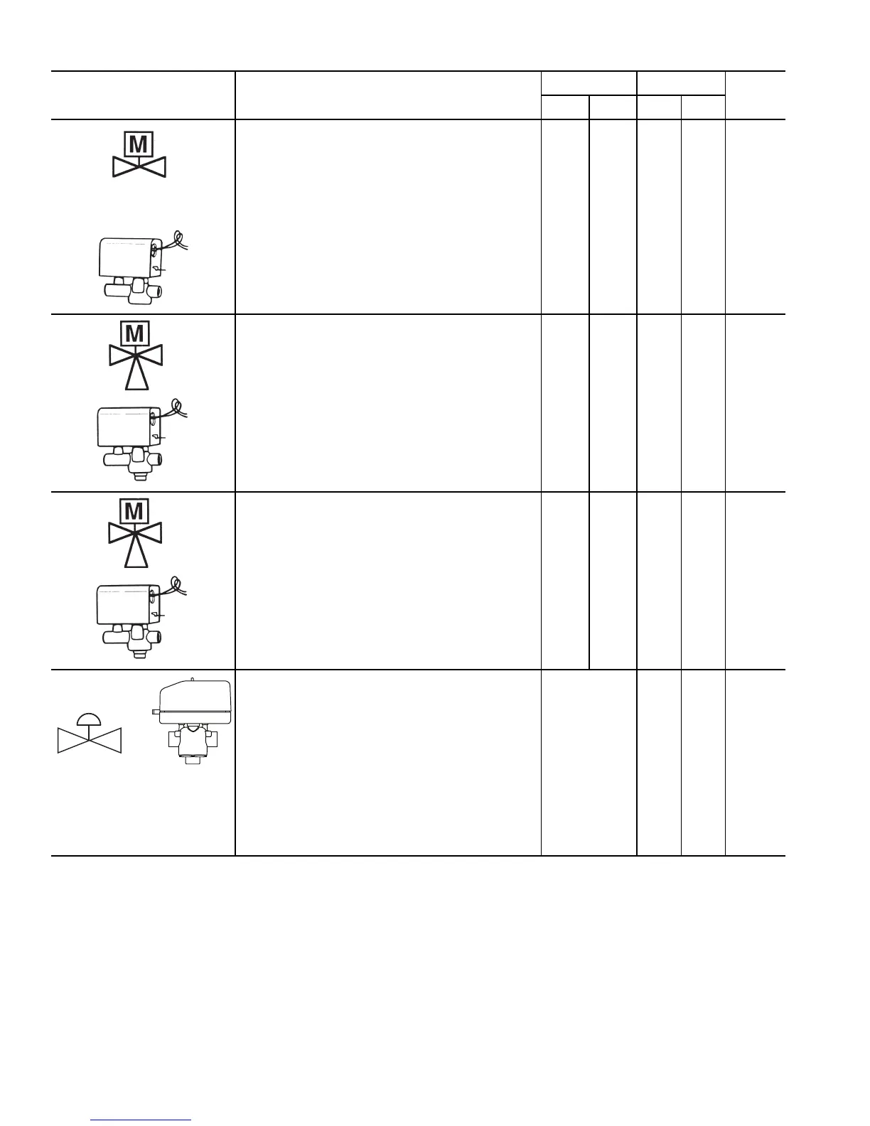
SYMBOL/SKETCH DESCRIPTION
C
V
FACTOR RATING*
STEAM
USE
1
/
2
3
/
4
PSI F
2-WAY MOTORIZED VALVE (150 PSI close off dif-
ferential pressure): Electric 2-position flow control
valve (open/closed). Normally closed body with man-
ual override lever. Installed in supply line to unit.
Application — All standard control and valve pack-
ages are based upon normally closed valves (valve
electrically powered open and closed by spring
return when electric power removed). Manual over-
ride lever allows valve to be placed in the open posi-
tion for secondary (unit) flushing, constant water flow
prior to start-up, etc. Manual override is automati-
cally disengaged when valve is electrically activated.
Consult factory for normally open valve applica-
tions.
4.9 10.3 300 240 NO
3-WAY MOTORIZED VALVE (25 PSI close off dif-
ferential pressure): Electric 2-position flow control
valve (closed to coil/open to bypass or open to coil/
closed to bypass). Normally closed with manual
override lever. Installed in supply line to unit.
Application — Same comments as 2-way motorized
valve except with manual override lever engaged the
valve is open to both ports and water flow will take
the path of least resistance through the valve pack-
age (not necessarily 100% through the coil).
4.0 4.0 300 200 N/A
3-WAY MOTORIZED VALVE (150 PSI close off dif-
ferential pressure): Electric 2-position flow control
valve (closed to coil/open to bypass or open to coil/
closed to bypass). Normally closed with manual
override lever. Installed in supply line to unit.
Application — Same comments as 2-way motorized
valve except with manual override lever engaged the
valve is open to both ports and water flow will take
the path of least resistance through the valve pack-
age (not necessarily 100% through the coil).
4.9 4.9 300 240 N/A
MODULATING VALVE (Optional)
(Non-Spring Return, Floating Point Actuator):
Modulating valves are designed to control the flow in
the circuit by making incremental adjustments to the
flow path within the valve.
Application — To control fluid flow in fan coil units.
On the 42DD commercial fan coil models, the factory
provided modulating valve has application restric-
tions. In these models, the valve packages are
located in the airstream, downstream of the coil. Due
to the ambient temperature limitations of the modu-
lating valves, the valves can only be used in the units
listed above with 2-pipe cooling only systems.
4.0 300 200
N/A
C
v
— Coefficient of Velocity
DX — Direct Expansion
ETO — Engineering to Order
 Loading...