55
CHECKING AND REPAIRING OF ELECTRIC PARTS
9
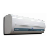
Operating Procedure Photos
Fig. 1
Fig. 2
1) Measuring insulation resistance of indoor fan
motor
a Remove the fan motor connector from PCB.
b Connect clip to the ground terminal
connecting Green/Yellow line.
c Measure insulation resistance by connecting
terminal of insulation ohmmeter to the arbitrary
fan motor connector. (Refer to fig. 1)
d It is normal that insualtion resistance is over
1MΩ.
2) Checking the winding of compressor motor
a. After removing terminal cover of compressor
motor, set the range of resistance measurement
of multimeter to "x1Ω".
b. Among the terminals, check the disconnection
between two terminals (C R, C S)as shown
in fig. 2.
c. Check the disconnection between two terminals
(1 3) of Overload-protector of compressor motor.
d. It is normal if there is no disconnections.
3) Checking PCB for control by operating voltage
of fan motor
a. Remove the connector between PCB and fan
motor.
b. Assure that other parts are not short before
supplying power to the unit.
c. Operate the unit and change fan speed by remote
controller.
d. It is normal that the voltage between the
connector pin (CN3, ) is measured as
over (line voltage - 50VAC). But, this test has to be
done within 1 minute.
 Loading...