Do you have a question about the Carrier 42NQV009E and is the answer not in the manual?
Operational parameters for the 42NQV009E/38NYV009E and 42NQV012E/38NYV012E models.
Graphical representation of cooling and heating performance curves.
Critical safety precautions for handling R410A refrigerant.
Guidelines for refrigerant pipe setup, materials, and processing.
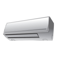
Physical dimensions and layout of the indoor unit.
Physical dimensions and layout of the outdoor unit.
Electrical schematics and connections for the indoor unit.
List of electrical components and their specifications for the indoor unit.
Visualizing the refrigerant flow path within the system.
Key performance data under various operating conditions.
Control system logic and components for the indoor unit.
Overall control strategy and system architecture.
Detailed description of various operation modes.
Critical safety guidelines and precautions for installation.
Step-by-step instructions for installing the indoor unit.
Initial troubleshooting checks and basic diagnostic steps.
Interpreting error codes via indoor unit LED indicators.
Using the remote control for system diagnostics.
Troubleshooting based on observed operational symptoms.
Diagnosis of specific error codes for miswiring and leaks.
Procedures for replacing main parts of the indoor unit.
Procedures for replacing main parts of the outdoor unit.
Exploded view and parts list for the indoor unit assembly.
Detailed parts list for the outdoor unit model 38NYV009E.
| Brand | Carrier |
|---|---|
| Model | 42NQV009E |
| Category | Air Conditioner |
| Language | English |


