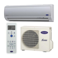
Do you have a question about the Carrier 42NQV025M and is the answer not in the manual?
Safety precautions specific to handling R410A during installation and servicing.
Guidelines and requirements for installing refrigerant piping with R410A.
Exploded view and dimensions of the indoor unit assembly.
Exploded view and dimensions of the outdoor unit assembly.
Detailed wiring diagram for the indoor unit, including connections and components.
Detailed wiring diagram for the outdoor unit, including connections and components.
Specifications of electrical parts used in the indoor unit.
Specifications of electrical parts used in the outdoor unit.
Schematic representation of the refrigerant circuit for cooling and heating.
Table of operational data under various temperature conditions.
Control block diagram for the indoor unit and its functions.
Control block diagram for the outdoor unit and its functions.
Overview of the air conditioner's control system and component roles.
Explains basic and specific operation modes like cooling, heating, and dry.
How to set and use the auto restart feature after power failure.
Details on remote control functions, operations, and indicators.
Explanation of the Hi-POWER mode for faster cooling or heating.
Visual guide for positioning and connecting indoor and outdoor units.
Lists optional parts required for installation.
Lists standard accessories and installation parts included with the unit.
Lists specialized tools required for installation and servicing of R410A systems.
Procedures and considerations for installing the indoor unit.
Procedures and considerations for installing the outdoor unit.
Initial checks for power supply and voltage before deeper diagnosis.
Methods for initial fault assessment using LEDs and symptoms.
Interpreting LED indicators for self-diagnosis of unit status.
Using the remote controller to access and interpret diagnostic check codes.
Diagnosing problems based on specific symptoms observed in the indoor unit.
Troubleshooting specific error codes related to wiring and sensor faults.
Methods for checking the condition of key internal components like P.C. boards.
Diagnostic procedures focused on the outdoor unit and its components.
Procedure to test the outdoor fan motor for proper function.
Procedures for replacing parts of the indoor unit, such as the front panel and electrical components.
Details on replacing the microcomputer or P.C. board assembly.
Procedures for replacing parts of the outdoor unit, including cabinets and assemblies.
Exploded view and parts list for indoor unit E-assembly.
Exploded view and parts list for the main indoor unit components.
Exploded view and parts list for the outdoor unit.
Exploded view and parts list for outdoor unit E-assembly.
| Brand | Carrier |
|---|---|
| Model | 42NQV025M |
| Category | Air Conditioner |
| Language | English |


