Do you have a question about the Carrier 42NQV025H and is the answer not in the manual?
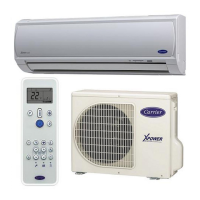
Details unit specifications including capacity, power, and noise levels.
Graphs showing operational characteristics based on compressor speed and temperature.
Charts illustrating how capacity changes with outdoor temperature.
Precautions for safe installation and servicing procedures for R410A.
Guidelines for installing refrigerant piping, including materials and joints.
Lists required and general tools for R410A installation and servicing.
Step-by-step procedure for recharging refrigerant, including safety precautions.
Details on materials and procedures for brazing pipes, including flux usage.
Dimensional drawings and installation details for the indoor unit.
Dimensional drawings and installation details for the outdoor unit.
Lists electrical parts and their specifications for the indoor unit.
Lists electrical parts and their specifications for the outdoor unit.
Diagram illustrating the refrigerant flow for cooling and heating operations.
Table showing operational data for cooling and heating conditions.
Block diagram illustrating the control functions of the indoor unit and remote controller.
Block diagram illustrating the control functions of the outdoor unit.
Details various operation modes like basic, cooling, heating, auto, and dry.
Describes how to set and use the auto restart feature after power failure.
Explains the display of room and set temperatures on the 7-segment display.
Covers the functions and operations of the remote controller.
Diagrams showing the layout for installing indoor and outdoor units.
Lists optional parts, accessories, and tools required for installation.
Instructions for installing the indoor unit, including placement and drilling.
Guidelines for installing the outdoor unit, including placement and refrigerant addition.
Initial checks for power supply and voltage to confirm basic operation.
Methods for initial diagnosis using LED indicators, remote controller, and symptoms.
Interpreting LED flash codes for self-diagnosis of indoor unit issues.
Using the remote controller in service mode to retrieve check codes for diagnosis.
Troubleshooting common symptoms like no power or fan issues.
Diagnosing problems related to wiring between indoor and outdoor units.
Troubleshooting specific error codes related to miswiring and gas leaks.
Procedures for diagnosing issues within the outdoor unit's inverter assembly.
Methods for checking main components like the P.C. board.
Steps to diagnose the condition of the outdoor fan motor.
Procedures for disassembling and replacing parts of the indoor unit.
Steps to access and replace the microcomputer on the indoor unit's P.C. board.
Procedures for detaching and attaching parts of the outdoor unit.
Exploded view and parts list for the indoor unit.
Exploded view and parts list for indoor unit electronic parts assembly.
Exploded views of the outdoor unit with part identification.
| Refrigerant | R-410A |
|---|---|
| Heating Capacity | 2.8 kW |
| Energy Efficiency Ratio (EER) | 3.21 |
| Outdoor Unit Dimensions (LxWxH) | 780 x 540 x 250 mm |
| Power Supply | 220-240V, 50Hz |
| HSPF Rating | Not available |
| Outdoor Unit Dimensions (H x W x D) | 540 x 780 x 250 mm |