Do you have a question about the Carrier 42NQV045H and is the answer not in the manual?
Essential safety precautions for installation, operation, and servicing of the air conditioner.
Technical specifications including capacity, electrical data, dimensions, and noise levels.
Safety precautions specific to R410A refrigerant, focusing on pressure and impurity control.
Lists tools exclusive to R410A and general tools for installation and servicing procedures.
Exploded views and diagrams illustrating the physical layout and dimensions of the indoor unit.
Exploded views and diagrams showing the physical layout and dimensions of the outdoor unit.
Electrical schematics for specific indoor/outdoor unit model combinations.
Electrical schematics for specific indoor/outdoor unit model combinations.
Details on electrical parts for the indoor unit, including motors, sensors, and their ratings.
Diagrams illustrating refrigerant flow paths for 42NQV025H/38NYV025H and 42NQV035M/38NYV035M.
Tables summarizing performance data under various temperature conditions for cooling and heating.
Schematic showing the MCU functions and signal flow for the indoor unit.
Diagram illustrating the microcomputer control functions and signal flow for the outdoor unit.
General explanation of the control system, roles of indoor/outdoor units, and compressor control.
Explains various operation modes including basic, cooling/heating, AUTO, DRY, and fan speed control.
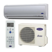
Details on remote control operations, button functions, and display indicators for user interaction.
Visual guide for installing indoor and outdoor units, including placement and connection points.
Lists and describes optional parts, accessories, and tools required for installation.
Highlights tool changes and requirements specific to R410A refrigerant systems.
Specific guidance on indoor unit placement, drilling holes, and mounting the installation plate.
Instructions for safe electrical connections and wiring the indoor unit to the power supply.
Procedures for routing refrigerant pipes, insulating them, and connecting the drain hose.
Guidelines for selecting outdoor unit location and precautions for adding refrigerant.
Instructions for water drainage from the outdoor unit and connecting refrigerant pipes using flaring.
Procedures for system evacuation and connecting electrical wiring to the outdoor unit.
Steps for conducting a system test operation and configuring remote controller settings.
Basic checks for power, voltage, and normal operation before detailed troubleshooting.
Initial troubleshooting steps and interpreting indoor unit LED patterns for fault identification.
Using the remote controller's service mode to retrieve check codes for fault diagnosis.
Safety notes for servicing and a table detailing check codes, causes, and actions.
Step-by-step diagnosis for common indoor unit operational symptoms.
Diagnostic procedures for identifying and resolving issues with the remote controller.
Troubleshooting guide for faults related to interconnecting and serial signal wiring.
Specific troubleshooting steps for check codes related to miswiring and refrigerant issues.
Flowchart for diagnosing problems within the outdoor unit's inverter assembly.
Procedures for checking the indoor unit's P.C. board and related components.
Layouts of P.C. boards and resistance values for checking sensors and motors.
Procedures for checking electrolytic capacitors and diode blocks using a multimeter.
Guide to diagnose whether the outdoor fan motor is functional or faulty.
General steps for disassembling the indoor unit to access main parts for replacement.
Detailed instructions for removing and reassembling the indoor unit's front panel.
Steps for removing and replacing the indoor unit's electric parts box assembly.
Procedures for replacing the horizontal louver and the evaporator (heat exchanger).
Instructions for removing and replacing the bearing component of the indoor unit.
Steps for removing and replacing the indoor unit's fan motor.
Procedures for installing the cross flow fan and motor, including positioning.
Common procedures for accessing and replacing the microcomputer or P.C. board.
Steps for detaching and attaching the outdoor unit's upper cabinet and valve cover.
Procedures for removing and attaching the front cabinet of the outdoor unit.
Steps for checking and replacing the inverter assembly, including capacitor discharge.
Instructions for disconnecting and replacing the control board assembly.
Procedures for replacing the side cabinets and the outdoor fan motor.
Steps for removing and replacing the compressor and reactor.
Procedures for replacing the electronic expansion valve coil and the fan guard.
Guides for installing and attaching TE, TS, TD, and TO sensors correctly.
A list of parts for the indoor unit, with location numbers and descriptions.
A list of electronic components for the indoor unit with location and part numbers.
A list of parts for the outdoor unit, with location and part numbers.
Diagrams showing the layout of P.C. boards for various unit models.
| Brand | Carrier |
|---|---|
| Model | 42NQV045H |
| Category | Air Conditioner |
| Language | English |