<Inspection procedure>
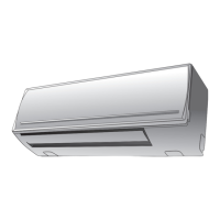
1. Remove the front panel. (Remove 2 screws.)
2. Remove the cover of the fan motor lead wires.
3. Check AC voltage with CN31 connector while the fan motor is rotating.
NOTE :
• Using a tester, measure the resistance value of each winding coil.
• Use a thin test rod.
ate" of "Judgment of Trouble by Every Symptom".
AFS-220-20-4AR
• Do not disconnect the connector while the fan motor is rotating.
• For P.C. board side, proceed to the item "Only indoor fan does not oper-
1
3
5
1
2
3
2
1
3
2
1
3
2
1
3
2
1
3
CN31
CN33
P.C. board
WHI
BLK
RED
BLK
RED
WHI
BLU
PUR
GRY
BLU
PUR
GRY
Resistance value
Position (P.C. board)
Between 3 (Black) - 1 (Red)
Between 3 (Black) - 5 (White)
Between 1 (Red) - 5 (White)
74
±
15
Ω
100
±
20
Ω
174
±
35
Ω
BLK
WHI
RED
PUR
GRY
BLU
(For AC fan motor in 42NQV025H, 42NQV035H, 42NQV035M)
– 78 –
FILE NO. SVM-07013

 Loading...


