Manufacturer reserves the right to discontinue, or change at any time, specifications or designs without notice and without incurring obligations.
Catalog No. 04-53420024-01 Printed in U.S.A. Form 42S-5SI Pg 1 9-22 Replaces: 42S-4SI
Installation, Start-Up and Service
Instructions
CONTENTS
Page
SAFETY CONSIDERATIONS . . . . . . . . . . . . . . . . . . . 1
INTRODUCTION . . . . . . . . . . . . . . . . . . . . . . . . . . . . . . 2
PHYSICAL DATA . . . . . . . . . . . . . . . . . . . . . . . . . . . . . 2
PRE-INSTALLATION . . . . . . . . . . . . . . . . . . . . . . . . . . 2
Unpack and Inspect Units . . . . . . . . . . . . . . . . . . . . . 2
Un
it Protection from Damage . . . . . . . . . . . . . . . . . . 2
Prepare Jobsite for Unit Installation . . . . . . . . . . . . . 3
Identify and Prepare Units . . . . . . . . . . . . . . . . . . . . . 3
Unit Clearance and Service Access . . . . . . . . . . . . . 3
INSTALLATION . . . . . . . . . . . . . . . . . . . . . . . . . . . . . 17
Step 1 — Place Units in Position . . . . . . . . . . . . . . . 17
• 42SG, SH, AND SJ UNITS
• 42SUA UNIVERSAL STACK ARRANGEMENT
• 42SMA FURRED-IN MEGA UNITS
Step 2 — Make E
lectrical Connections . . . . . . . . . . 25
• FACTORY-INSTALLED OPTIONS
• STANDARD WIRING PACKAGES
Step 3 — Make Duct Connections . . . . . . . . . . . . . 26
Step 4 — Frame and Finish Unit . . . . . . . . . . . . . . . 26
• CONCEALED UNIT ENCLOSURE
• EXPOSED UNIT FINISH, TOUCH-UP AND REPAINT
Step 5 — Cut Out Openings for Grilles and
Thermostats . . . . . . . . . . . . . . . . . . . . . . . . . . . . . 26
Step 6 — Make Final Preparations . . . . . . . . . . . . . 27
• ECM (ELECTRONICALLY COMMUTATED MOTOR)
CONTROL OPTION
START-UP . . . . . . . . . . . . . . . . . . . . . . . . . . . . . . . . . 28
COO
LING/HEATING SYSTEM . . . . . . . . . . . . . . . . . 29
Direct Expansion (DX) Systems . . . . . . . . . . . . . . . . 29
Air System Balancing . . . . . . . . . . . . . . . . . . . . . . . . 29
Water System Balancing . . . . . . . . . . . . . . . . . . . . . 29
Water Treatment . . . . . . . . . . . . . . . . . . . . . . . . . . . . 29
Controls Operation . . . . . . . . . . . . . . . . . . . . . . . . . .
30
SERVICE . . . . . . . . . . . . . . . . . . . . . . . . . . . . . . . . . . 30
Excessive Condensation on Unit . . . . . . . . . . . . . . 30
To Clean Coil . . . . . . . . . . . . . . . . . . . . . . . . . . . . . . . 30
Check Drain . . . . . . . . . . . . . . . . . . . . . . . . . . . . . . . . 30
Fan Motor Bearings . . . . . . . . . . . . . . . . . . . . . . . . . 30
Motor/Blower Assembly . . . . . . . . . . . . . . . . . . . . . . 30
Clean Fan Wheel . . . . . . . . . . . . . . . . . . . . . . . . . . . . 30
Electric Resistance Heater Assembly . . . . . . . . . . . 31
Electrical Wiring and Controls . . . . . . . . . . . . . . . . . 31
Valves and Piping . . . . . . . . . . . . . . . . . . . . . . . . . . . 31
Filters, Throwaway . . . . . . . . . . . . . . . . . . . . . . . . . . .31
Filters, Permanent .
. . . . . . . . . . . . . . . . . . . . . . . . . .31
Drain . . . . . . . . . . . . . . . . . . . . . . . . . . . . . . . . . . . . . .31
Replacement Parts . . . . . . . . . . . . . . . . . . . . . . . . . . .31
Warranty . . . . . . . . . . . . . . . . . . . . . . . . . . . . . . . . . . .31
• VARIABLE AIRFLOW FOR 0-10VDC
• ECM VARIABLE AIRFLOW FOR 0-10VDC
APPENDIX A — BLOCK-OUT CONSTRUCTION. . . .32
APPENDIX B — POTENTIOMETER
ADJUSTMENT . . . . . . . . . . . .
. . . . . . . . . . . . . . . 35
APPENDIX C — CONTROL OPERATIONS . . . . . . . .36
APPENDIX D—EVO/ECM 4-SPEED
ADJUSTMENT . . . . . . . . . . . . . . . . . . . . . . . . . . . . . .41
START-UP CHECKLIST FOR 42S SERIES FAN COIL
AIR CONDITIONERS . . . . . . . . . . . . . . . . . . . . . . . .CL-1
SAFETY CONSIDERATIONS
Installation and servicing of air-conditioning equipment can be
hazardous due to system pressure and electrical components. Only
trained and qualified service personnel should install, repair, or
service air-conditioning equipment.
Untrained personnel can perform basic maintenance functions of
cleaning coils and filters and replacing filters. All other operations
should be performed by trained service personnel. When working
on air-conditioning equipment, observe precautions in the
literature, tags and labels attached to the unit, and other safety
precautions that may apply.
Follow all safety codes. Wear safety glasses and work gloves. Use
quenching cloth for unbrazing operations. Have fire extinguisher
available for all brazing operations.
It is important to recognize safety information. This is the safety-
alert symbol . When you see this symbol on the unit and in
instructions or manuals, be alert to the potential for personal
injury.
Understand the signal words DANGER, WARNING, CAUTION,
and NOTE. These words are used with the safety-alert symbol.
DANGER identifies the most serious hazards which will result in
severe personal injury or death. WARNING signifies hazards
which could result in personal injury or death. CAUTION is used
to identify unsafe practices, which may result in minor personal
injury or product and property damage. NOTE is used to highlight
suggestions which will result in enhanced installation, reliability,
or operation.
IMPORTANT: Children should be supervised to ensure that
they do not play with appliance.
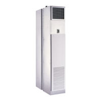
42S Series
Stack Model
Fan Coil Air Conditioners