12
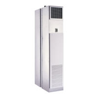
Fig. 10 — 42SUA Universal Furred-In Stack Unit Dimensions
Side panel dimmed for clarity.
4-Pipe panel shown.
NOTE: Risers removed for clarity.
Standard heights and widths
shown for riser penetration.
See Note 10.
Control Box Option with E Heat
6-5/8
[168]
6/5-8
[168]
SUA
SUA
3
[76]
3
[76]
1-1/8
[27]
D
H
C
H
A
F
B
1
[25]
51
[1289]
63
[1598]
3-1/4
[83]
3-1/4
[83]
Ø4
[102]
E
Tail
Piece
8
[202]
E
I
88
[2233]
Note 7
3.00
[76.2]
9
[288]
1-1/2
[38]
3-1/2
[88.9]
39
[991]
5
[127]
LEGEND
CR— Cold Water Return
CS — Cold Water Supply
D — Drain
HR— Hot Water Return
HS — Hot Water Supply
R — Return
S — Supply
ITEM DESCRIPTION
1 Supply KO’s Top/Sides
2 Filter
3 Control Box
4 Electrical Knock Outs
5 Coil 1/2 in. [13] OD
6 Drain Pan
7 Flex Drain Tube/P-Trap
8 Motor/Blower Housing
9 Return Air Opening
10
Outside Air Knockout (s) Side
Panels
11 Access Panel (Control Box)
12 Riser, Supply and Return
13 Riser, Drain
14 Isolation Ball Valves
15 Strip Heater (Optional E Heat)
16
Heat Limit Switch
(Optional E Heat)
17 Heat Shield (Optional E Heat)
18 Service Switch (Optional)
NOTES:
1. Units are fabricated of galvanized steel with a 16 gauge galvanized fan deck.
2. All risers are insulated.
3. Thermostats shipped loose for field connection.
4. Risers are factory piped to coil with valves as specified.
5. Blower, motor, valves, coil, and filter are accessible through the return air opening.
6. Unit and control box are insulated.
7. Riser length = [(floor to floor) + 2 in. (51)], maximum riser length = 119 in. [3023]. Consult
project submittal for riser specifications.
8. Maximum riser size is 3 in. (76). If larger sizes are required, please consult the factory.
9. Expansion loops in hot water heating circuits as required.
10. Riser slot knock-outs provided on 3 sides of the cabinet for coil connection to permit expan-
sion and contraction of risers. Coil connections to be at the center of slots.
11. Drain and riser knock-outs on 3 sides of cabinet.
12. All dimensions are in inches [mm].
UNIT
SIZE
DIMENSIONS — in. [mm]
SIDE/FRONT
SUPPLY
TOP SUPPLY DIMENSIONS CONNECTIONS
A B C D E F H I Coil Drain
03
14 [356] 12 [305] 14 [356] 10 [254] 17 [432] 1-1/2 [38] 1-1/2 [38] 14 [356]
1/2 [13]
SWT x Hose
Adapter
7/8 [22] ID
EPDM Tube
04
06
18 [457] 12 [305] 16 [406] 12 [305] 20 [508]
1 [25]
2 [51] 18 [457]
08
10
22 [559] 16 [406] 18 [457] 16 [406] 24 [610] 3 [76] 22 [559]
12

 Loading...