TO LIGHT UNIT
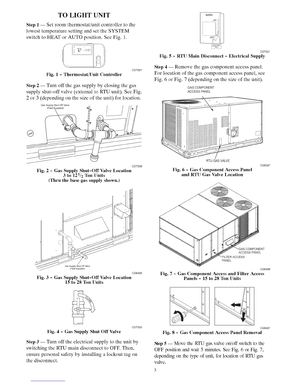
Step 1 1 Set room thermostat/unit controller to the
lowest temperature setting and set the SYSTEM
switch to HEAT or AUTO position. See Fig. 1.
Fig. 1 - Thermostat/Unit Controller
C07381
Step 2 1 Turn off the gas supply by closing the gas
supply shut-off valve (external to RTU unit). See Fig.
2 or 3 (depending on the size of the unit) for location.
Gas Supply Shut Off Valve
Jpplied)
[MA,Ni[
....oF,¢_?_,
C07831
Fig. 5 - RTU Main Disconnect - Electrical Supply
Step 4 1 Remove the gas component access panel.
For location of the gas component access panel, see
Fig. 6 or Fig. 7 (depending on the size of the unit).
GASCOMPONENT
ACCESS PANEL
®
C07358
Fig. 2 - Gas Supply Shut-Off Valve Location
3 to 121/2 Ton Units
(Thru the base gas supply shown.)
RTU GAS VALVE
Fig. 6 - Gas Component Access Panel
and RTU Gas Valve Location
C08397
Gas Supply Shut OffValve
(Field Supplied)
C08485
Fig. 3 - Gas Supply Shut-Off Valve Location
15 to 28 Ton Units
Fig. 4 - Gas Supply Shut Off Valve
C07330
Step 3 1 Turn off the electrical supply to the unit by
switching the RTU main disconnect to OFF. Then,
ensure personal safety by installing a lockout tag on
the disconnect.
)NENT
ACCESS PANEL
PANEL
C08486
Fig. 7 - Gas Component Access and Filter Access
Panels - 15 to 28 Ton Units
C08487
Fig. 8 - Gas Component Access Panel Removal
Step 5 1 Move the RTU gas valve on/off switch to the
OFF position and wait 5 minutes. See Fig. 6 or Fig. 7,
depending on the type of unit, for location of RTU gas
valve.

 Loading...


