Do you have a question about the Carrier 48HC D17 Series and is the answer not in the manual?
Explains DANGER, WARNING, and CAUTION terms used with safety symbols.
Details hazards like cut, unit damage, fire, explosion, shock, and operational alerts.
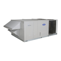
Shows general unit arrangement and access locations with diagrams.
Lists tasks for monthly, quarterly inspections, and seasonal checks.
Describes types of filters and their maintenance requirements.
Details the procedure for removing and replacing return air filters.
Instructions for cleaning inlet screens for outdoor air hood and economizer.
Describes fan assembly, motor mounting, and belt tension checking.
Procedures for adjusting belt tension and replacing the V-belt.
Guides on adjusting motor pulleys and changing fan speed.
Steps for proper alignment of fan and motor pulleys.
Information on fan system bearings and collar tightening.
Explains how the SAV system adjusts fan speed for cooling, heating, and ventilation.
Details how to identify if a unit has the VFD option based on model number.
Notes on installing units with the SAV option.
Step-by-step procedure for replacing a belt-driven motor.
Details on adjusting belt tension using an adjustment tool.
Explains how to change fan speed by adjusting pulley diameters.
Formula to determine variable pitch pulley diameter.
Description of coil construction and general maintenance recommendations.
Details on removing fibers, periodic rinsing, and routine cleaning.
Specific instructions for cleaning two-row condenser coils.
Description of coil construction and general maintenance recommendations.
Details on removing fibers, periodic rinsing, and routine cleaning.
Description of metering devices and troubleshooting for blockages.
Explanation of how the TXV adjusts refrigerant flow based on conditions.
Overview of the Humidi-MiZer system for improved dehumidification.
Description of Dehumidification (Subcooling) and Reheat Modes.
Description of the subcooler/reheat coil and its function.
Details the three sub-modes of operation for the Humidi-MiZer system.
Diagram showing refrigerant flow in normal cooling mode.
Diagram showing refrigerant flow in subcooling reheat mode.
Diagram showing refrigerant flow in hot gas reheat mode.
Table detailing inputs, outputs, and connections for the reheat control board.
Table summarizing inputs, modes, and outputs for system operation.
Table of common problems, causes, and remedies for Humidi-Mizer modes.
Explanation of how the TXV adjusts refrigerant flow based on conditions.
Procedure for replacing a TXV, including safety precautions.
Diagram and details for proper insulation of TXV sensor bulbs.
Diagrams showing the locations of TXV sensor bulbs.
Caution regarding POE oil's hygroscopic nature and contamination.
Procedures for charging the unit with refrigerant.
Guidance on using charging charts for proper refrigerant levels.
Instructions for using charging charts to determine correct superheat.
Chart for charging a 15-ton unit, Circuit A, based on suction temp and pressure.
Chart for charging a 15-ton unit, Circuit B, based on suction temp and pressure.
Chart for charging a 17.5-ton unit, Circuit A, based on suction temp and pressure.
Chart for charging a 17.5-ton unit, Circuit B, based on suction temp and pressure.
Chart for charging a 20-ton unit, Circuit A, based on suction temp and pressure.
Chart for charging a 20-ton unit, Circuit B, based on suction temp and pressure.
Chart for charging a 25-ton unit, Circuit A, based on suction temp and pressure.
Chart for charging a 25-ton unit, Circuit B, based on suction temp and pressure.
Information on compressor lubrication, mounting bolts, and rotation.
Procedure to determine and correct compressor rotation direction.
Procedure for replacing compressor and filter drier.
Steps to adjust the condenser fan height and tighten setscrews.
Refers to tables for troubleshooting cooling system topics.
Table listing cooling system problems, causes, and remedies.
Warning about electrical hazards when servicing convenience outlets.
Description of non-powered, unit-powered outlets and covers.
Information on the duty cycle limitation for the unit-powered outlet.
Overview of the smoke detector system components and function.
Description of the smoke detector controller housing and features.
Description of the smoke detector sensor components and operation.
Details on the location of supply air smoke detector sensors.
Location and installation of return air smoke detector without economizer.
Wiring and response details for FIOP smoke detectors.
How smoke detectors interact with PremierLink and RTU-Open controls.
Diagram showing return air sampling tube location with economizer.
Diagram illustrating typical smoke detector system wiring connections.
Procedures to test sensor and controller alarm initiation.
Procedures to test sensor/controller compensation for dirt.
How to configure dirty sensor test operation.
Procedure to test the test/reset station's ability to initiate an alarm state.
Procedure to test the test/reset station's ability to initiate a dirty sensor test.
Instructions for cleaning the duct smoke sensor.
Describes conditions when the smoke detector enters alarm or trouble states.
Describes the normal operating state of the smoke detector.
Details on overcurrent, overtemperature, and pressure protection.
Information on compressor mounting bolt torque.
Details on high and low-pressure switch trip/reset settings.
Details on Thermik and external overload breaker protection.
Notes on condenser fan motor and control circuit protection.
Description of the PremierLink controller's compatibility and function.
Details on the PremierLink controller's location and factory wiring.
Description, location, and installation of RTU-Open controller.
Installing sensors/accessories and finding troubleshooting guides for RTU-Open.
Diagram of the RTU-Open control module terminals and connections.
Description of the heat exchanger system, burners, and induced draft fan.
Details on natural gas and propane fuel types and pressure requirements.
Information on converting the unit for liquid propane fuel.
Limit switch function and instructions for inspecting flue gas passageways.
Procedure for cleaning the combustion-air blower.
Instructions for inspecting and adjusting main burners.
Diagram showing maximum orifice projection dimension.
Procedure for removing and replacing the gas train components.
Instructions for cleaning and adjusting burners and spark gap.
Description and adjustment of the 2-stage gas valves.
Steps to check unit operation and adjust manifold pressure.
Information on the direct spark ignition system and IGC board.
Table detailing LED error codes for the Integrated Gas Unit Controller.
Procedure and information on replacing unit orifices.
Diagram illustrating typical wiring for the Integrated Gas Unit Controller.
Table detailing IGC terminal connections and their functions.
Specifies minimum entering air temps for heat exchangers and thermostat wiring.
Diagram showing wiring for the Outdoor Air Lockout Thermostat.
Refers to tables for additional heating system troubleshooting topics.
Table listing heating problems, causes, and remedies.
Table detailing IGC board LED alarm codes and their meanings.
Diagrams showing component locations for EconoMi$er IV.
Diagrams showing component locations for EconoMi$er2.
Diagram illustrating EconoMi$er IV wiring connections.
Table defining input/output logic for EconoMi$er IV operation modes.
Details on the OAT sensor's function, range, and location.
Details on the SAT sensor's function, range, and location.
Information on the outdoor air lockout switch function.
Explanation of outdoor dry bulb changeover control logic.
Details on differential dry bulb control using an accessory sensor.
Explanation of outdoor enthalpy changeover control using sensors.
Chart showing enthalpy changeover setpoints based on temp and humidity.
Procedure for checking differential enthalpy control.
Information on using IAQ sensor for demand control ventilation.
Procedure for adjusting the exhaust fan setpoint.
Details on setting minimum damper position for ventilation.
Information on the damper movement time.
Criteria for selecting equipment for demand controlled ventilation.
Procedure for configuring the CO2 sensor settings.
Procedures for dehumidifying fresh air and preparing EconoMi$er IV.
Procedures to check differential and single enthalpy control.
Procedure to check DCV and power exhaust functions.
Procedure to return the EconoMi$er IV to normal operation.
Safety warnings and procedures for unit preparation before start-up.
Inspection of field accessories and RTU-OPEN alarms.
Checks for gas piping, refrigerant ports, filters, wiring, and compressor.
Steps for initiating cooling and main burner operation.
Electrical safety and software configuration for PremierLink.
Steps for performing a system check-out for PremierLink controls.
References for RTU-OPEN controller installation and setup guides.
Table listing torque values for various fasteners.
Guide to understanding the unit model number nomenclature.
Physical data for the refrigeration system, including charge and pressures.
Physical data for evaporator and Humidi-Mizer coils.
Physical data for evaporator fans, motors, and filters.
Physical data for horizontal fans, motors, and condenser coils.
Physical data related to the heating system operation.
Fan performance data for 48HC*D17 unit at various static pressures.
Fan performance data for 48HC*D20 unit at various static pressures.
Fan performance data for 48HC*D28 unit at various static pressures.
Horizontal fan performance for 48HC*D17 unit.
Horizontal fan performance for 48HC*D20 unit.
Horizontal fan performance for 48HC*D24 unit.
Horizontal fan performance for 48HC*D28 unit.
Vertical pulley adjustment settings for fan speed control.
Horizontal pulley adjustment settings for fan speed control.
Table listing wiring diagram part numbers for different unit configurations.
Control wiring diagram for 48HC units with various voltages.
Power wiring diagram for 48HC units with 208/230V.
Power wiring diagram for 48HC units with 460V.
Power wiring diagram for 48HC units with 575V.
Control diagram for 48HC units with Humidi-MiZer option.
Power diagram for 48HC units with Humidi-MiZer and 208/230V.
Power diagram for 48HC units with Humidi-MiZer and 460V.
Power diagram for 48HC units with Humidi-MiZer and 575V.
Control wiring diagram for the PremierLink system.
Control wiring diagram for PremierLink with Humidi-MiZer.
Wiring diagram for the RTU-OPEN control system.
Wiring diagram for RTU-OPEN with Humidi-MiZer system.
Diagrams showing MotorMaster sensor locations for D17, D20, and D24 models.
Diagrams showing MotorMaster sensor locations for D28 models.
Section for basic unit information like model, serial, and technician details.
Checklist for pre-start-up inspections and verifications.
Refer to service/maintenance manual for start-up instructions.
| Model | 48HC D17 Series |
|---|---|
| Series | 48HC |
| Type | Packaged Rooftop Unit |
| Refrigerant | R-410A |
| Compressor Type | Scroll |
| Phase | 3 |
| Voltage | 460V |
| Sound Level | 82 dB |



 Loading...