55
C06053
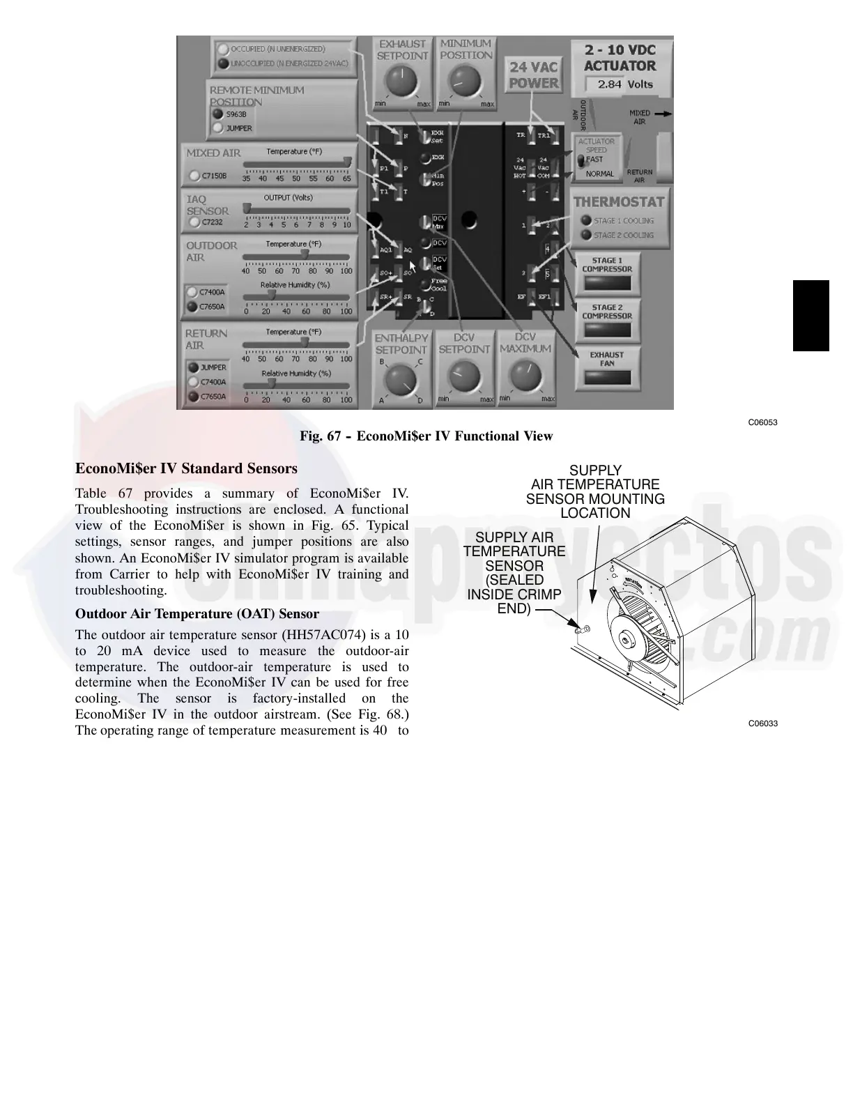
Fig. 67 -- EconoMi$er IV Functional View
EconoMi$er IV Standard Sensors
Table 67 provides a summary of EconoMi$er IV.
Troubleshooting instructions are enclosed. A functional
view of the EconoMi$er is shown in Fig. 65. Typical
settings, sensor ranges, and jumper positions are also
shown. An EconoMi$er IV simulator program is available
from Carrier to help with EconoMi$er IV training and
troubleshooting.
Outdoor Air Temperature (OAT) Sensor
The outdoor air temperature sensor (HH57AC074) is a 10
to 20 mA device used to measure the outdoor-air
temperature. The outdoor-air temperature is used to
determine when the EconoMi$er IV can be used for free
cooling. The sensor is factory-installed on the
EconoMi$er IV in the outdoor airstream. (See Fig. 68.)
The operating range of temperature measurement is 40_ to
100_F(4_ to 38_C). See Fig. 70.
Supply Air Temperature (SAT) Sensor
The supply air temperature sensor is a 3 K thermistor
located at the inlet of the indoor fan. (See Fig. 68.) This
sensor is factory installed. The operating range of
temperature measurement is 0 to 158_F(--18_ to 70_C).
See Table 68 for sensor temperature/resistance values.
SUPPLY AIR
TEMPERATURE
SENSOR
(SEALED
INSIDE CRIMP
END)
SUPPLY
AIR TEMPERATURE
SENSOR MOUNTING
LOCATION
C06033
Fig. 68 -- Supply Air Sensor Location
The temperature sensor looks like an eyelet terminal with
wires running to it. The sensor is located in the “crimp
end” and is sealed from moisture.
Outdoor Air Lockout Sensor
The EconoMi$er IV is equipped with an ambient
temperature lockout switch located in the outdoor
airstream which is used to lock out the compressors below
a42_F(6_ C) ambient temperature. (See Fig. 63.)
EconoMi$er IV Control Modes
IMPORTANT:
The optional EconoMi$er2 does not include
a controller. The EconoMi$er2 is operated by a 4 to 20
mA signal from an existing field-supplied controller. See
Fig. 64 for wiring information.
Determine the EconoMi$er IV control mode before set up
of the control. Some modes of operation may require
different sensors. (See Table 19.) The EconoMi$er IV is
48HC

 Loading...


